White Paper
Three Ways that Allegro TimingVision Environment Speeds Up Timing Closure of High-Speed PCB Interfaces
Overview
Introduction
On advanced high-speed interfaces, timing closure can be an iterative process that can be time-consuming and frustrating. PCB designers need techniques and tools to make the process more efficient, so they can contribute to an overall faster time to market for the design. This article discusses three ways that the new Cadence Allegro TimingVision environment speeds up timing closure of high-speed PCB interfaces.
Timing Closure: Why So Slow?
To support today’s smart, connected electronics products, PCB systems must perform faster, provide more bandwidth, and consume less power than ever before. The faster the signals, the more sensitive they are, so careful planning is a must. PCB systems are also incorporating more standards-based interfaces, like DDR3, DDR4, and PCI Express. As a result, PCB designers must address an increasingly complex set of electrical and layout implementation constraints, which makes timing closure a laborious, time-consuming process.
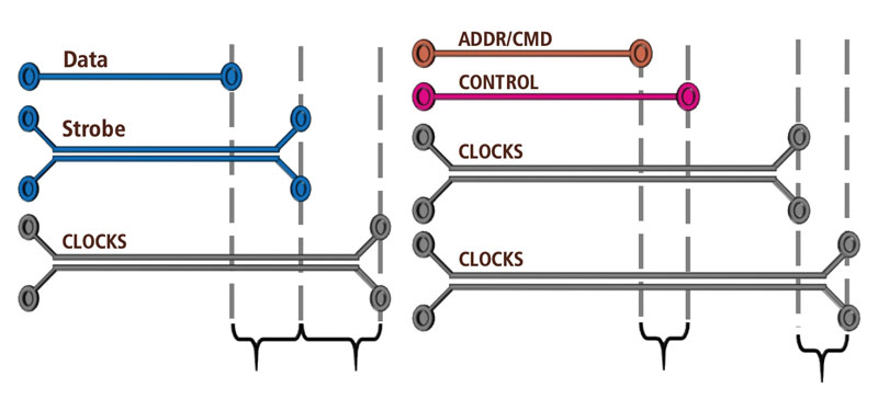
For example, consider the timing relationship for DDR3, as shown in Figure 1. DDRx interfaces have four sets of clocks and eight sets of strobes. There are complex matching requirements: the designer must match the clocks, strobes, and data, as well as the clocks, ADDR/CMD, and control. A change in one section of the groups has a ripple impact on the others. With smaller end-product footprints, signals are closer together. With the increase in operating frequencies, there are much tighter margins. Therefore, PCB designers must be careful in planning their tuning and routing, choosing the right set of signals to tune first. Otherwise, they risk thrashing between multiple sets of signals that have to match timing with common signals such as clocks and strobes.
Traditional Timing Closure Process
Timing closure can be an iterative process if not planned correctly—the designer fixes one byte lane, then another, and then goes back to the first lane to make any necessary adjustments based on any impact from changes on that second lane. With a traditional timing closure process, PCB designers must constantly shift between their design canvas and their design constraint management tool, such as Cadence Allegro Constraint Manager.
Allegro Constraint Manager provides feedback on a matched group level: all signals must meet timing in order for the group to show as “meeting constraints” (signals go green). However, neither the design canvas nor the constraint management tool provides visual feedback on how signals might be affected as the designer makes adjustments. So, the designer, viewing the data on Allegro Constraint Manager, must look at three to four different matched groups or multiple Allegro Contraint Manager sheets to understand all of the timing rules and ideal lengths for a signal. They must also perform multiple calculations in order to determine interdependencies and margins between groups of signals.
What is the Allegro TimingVision Environment?
Cadence’s Allegro TimingVision environment streamlines the timing closure process for high-speed PCB interfaces by consolidating onto the design canvas all of the data around timing rules and ideal signal lengths. Available within Cadence Allegro PCB Designer High-Speed Option, the Allegro TimingVision environment has demonstrated the ability to speed up timing closure by up to 67%. When used with Cadence’s Sigrity power-aware signal integrity analysis tool, the combined technologies help designers to quickly tune their signals in compliance with the latest memory interface specifications.
Pegatron, a Taipei-based electronics manufacturing company, had been spending a lot of time manually routing and tuning the traces on the PCBs the company develops for notebooks, tablets, and servers. Wanting to automate its routing process, Pegatron implemented the auto-interactive routing technology in the Allegro PCB Designer High-Speed Option (this technology is now integrated into the Allegro TimingVision environment). As a result, the company gained a 67% faster routing process and reduced by 75% the engineering resources needed for routing and tuning, freeing staff to work on other projects.
Three Key Capabilities in Allegro TimingVision Environment
Let’s take a closer look at three key capabilities in the Allegro TimingVision environment that contribute to the tool’s performance.
Embedded timing engine
Using an embedded timing engine, the Allegro TimingVision environment analyzes the whole interface structure and develops new timing goals to help PCB designers visualize real-time delay and phase information directly on the design canvas. The new timing goals and visual feedback allow the PCB designer to develop a strategy for tuning the signals in complex interfaces like DDR3 and DDR4, eliminating the time-consuming and frustrating iterative process.
Analyzing signal interdependencies, the engine develops delay and phase targets based on already completed point-to-point connections. With this data, PCB designers can develop the optimal strategy to address timing issues. Static and dynamic phase must be matched between the two signals of a differential pair to avoid crosstalk influence.
Real-time visual feedback on the design canvas
With this capability, designers get color-coded timing and phase information on the signals directly on their canvas. They also get customized data tips, and can see beyond the physical routing. Green means the signal meets the specifications, while red means it’s too short and yellow means the signal is too long. Target signals chosen by the PCB designer are shown as purple with a stipple fill pattern.
Auto-interactive routing technologies
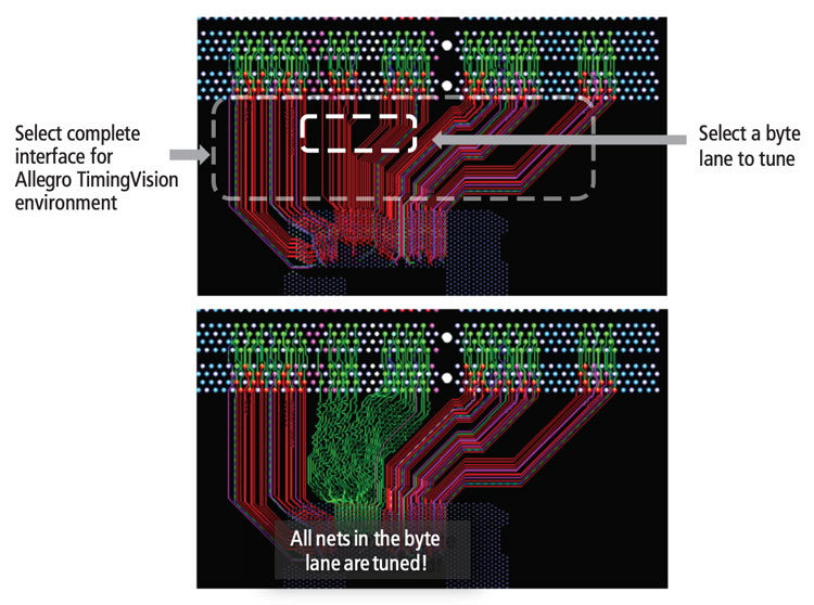
Auto-interactive Phase Tuning (AiPT) and Auto-interactive Delay Tuning (AiDT) help reduce manual work substantially. AiPT automatically matches dynamic and static phases for the differential pairs selected. The capability provides several options for trace lengthening and shortening, as well as pad entry/exit options. With AiPT, engineers benefit from substantially shorter matching time. AiDT automatically generates tuning patterns on a user-selected routed byte lane or interfaces, based on user-defined timing constraints and tuning parameters. AiDT also has a push/shove engine to create space necessary for tuning patterns. With AiDT, engineers can quickly tune a selected set of signals in just minutes versus the hours that such a task would require if performed manually.
Two Operating Modes
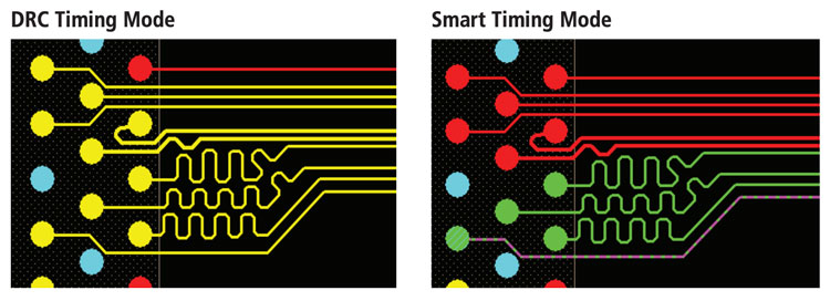
The Allegro TimingVision environment features two handy modes of operation, Smart Timing Mode and DRC Timing Mode.
Smart Timing Mode analyzes all of the timing interdependencies and calculates new targets for achieving timing closure. PCB designers then know whether signals need to be elongated, shortened, or are already within spec. This is especially beneficial at the beginning of the timing closure process as it is difficult to reconcile all of the interdependent timing relationships.
DRC Timing Mode communicates whether or not the design meets actual final timing constraints. This mode is to be used near the completion of a design for final validation. At this point, the visualization communicates adherence only when all the interdependencies are resolved.
In either mode, engineers can utilize a “Heads-up Display” meter while they are tuning and editing, to see when the signals are in compliance. With coloring, stipples, and design tips, actionable and consolidated information is shown right on the design canvas.
Summary
The Allegro TimingVision environment can remove a lot of the frustration and time-consuming back-and-forth process traditionally associated with timing closure. With its embedded timing engine, real-time visual feedback, and auto-interactive routing technologies, the tool helps PCB designers accelerate timing closure of high-speed PCB interfaces significantly—contributing to an overall faster time to market for the PCB design.