White Paper
SLAM and DSP Implementation
When automobiles were first introduced, they were used only for transportation—to quickly get from point A to point B. While this was revolutionary and changed the landscape as humans know it, there were more innovations to come. Automobiles have become smarter as more intelligence has been added, starting first with driver assistance applications, such as anti-lock brakes and power steering. Now, with artificial intelligence (AI), self-driving vehicles are on the horizon. One of the key ingredients to autonomous vehicles (AVs) is the ability to track the location and movement of the vehicle.
Overview
Introduction
With the introduction of GPS technology in the 1990s, tracking movement became a relatively easy task. This technology opened the door to several navigation- and route-planning applications. GPS does have its limitations, however. It is accurate only to within a few meters, thereby restricting its use to applications in which tracking small or “micro-movements” is not necessary. And, in certain areas where access to GPS satellites is limited (cities with tall buildings, mountains, etc.), the device might not have access to the data that GPS supplies, nullifying its use. As vehicles are becoming more autonomous and “aware” of their surroundings, tracking these micro-movements is now becoming necessary; therefore, we must look beyond what GPS offers.
Fortunately, simultaneous localization and mapping (SLAM) can orient a device to within inches and doesn’t require satellite connectivity. SLAM is the computational problem of constructing a map in an unknown environment while simultaneously keeping track of a position (location and orientation) within that environment. SLAM comprises tracking six degrees of freedom (6DoF), which is composed of three degrees for position (up/down, back/forward, and right/left), and three for orientation (yaw, pitch, and roll) to understand the car or user’s position in an environment (Figure 1).

SLAM has extensive usages; for example, consider a mapping application. SLAM can be used to identify where a car or user is facing in an environment—for example, facing northwest at an intersection—then the application can tell the user whether to turn right or left. A simple GPS calculation only knows that the car is at an intersection; the application won’t know which way it is facing until it has already driven in the wrong direction.
SLAM
SLAM is quickly becoming an important advancement in embedded vision as it enables a device with the ability of location awareness. Using SLAM, a vehicle can not only track where it is heading or its direction (orientation), but also how it is moving within its surrounding environment (location, speed, and altitude).
Previously, computations for SLAM were typically performed with a camera sensor as the only form of input. This was known as Visual SLAM (VSLAM). But in the past few years, with a suite of additional sensors becoming available, SLAM has evolved to fusing additional sensor inputs.
A SLAM system works by tracking a set of points through successive camera frames and other sensor data to triangulate the camera’s 3D position, while simultaneously using this information to approximate camera (or another sensor) orientation. As long as there is a sufficient number of points being tracked through each frame, both the orientation of the sensor(s) and the structure of the surrounding physical environment can be rapidly understood.
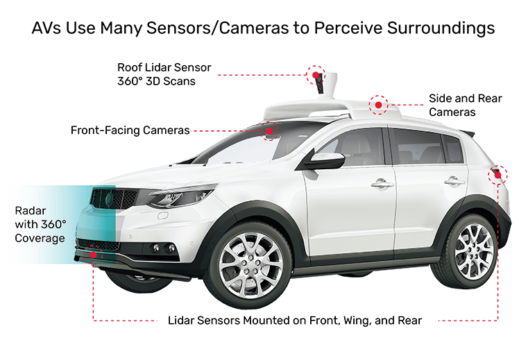
So, for example, in the case of automotive implementations, SLAM may use a combination of one or more forward-facing cameras, radar, lidar, and inertial measurement units (IMUs, which provide data from accelerometers and gyroscopes that help to estimate the sensor’s orientation) as inputs. SLAM is then used to determine how the vehicle is moving in the environment. When GPS data is available, it can be used to fortify the position estimate.
Figure 2 shows an example in which a variety of sensors, such as camera, lidar, and radar, is mounted around the vehicle that can be used as input for SLAM.
SLAM applications
SLAM is a key ingredient in many applications that are used for driver assistance and self-driving vehicles. A few of these applications include:
-
 Lane Keeping Assistance (and Lane Departure Warning): In addition to tracking lane markings on the road, SLAM is used to make sure the vehicle is traveling safely within a lane and to engage in lane changes safely.
 - Navigation: By understanding the surrounding environment combined with a planned route and GPS data, the vehicle can use SLAM to pilot itself to its destination.
- Forward Collision Warning (FCW): Combined with SLAM, the path or trajectory of the current vehicle can be used to for more robust collision warning.
Market trends for SLAM
As shown in Figure 3, the market size for SLAM-based applications is set to exceed $2 billion by 2024 [1]. Major drivers for this market growth are the advancements in SLAM algorithms and the growth of SLAM in various markets. The rising technological developments and growing awareness regarding the benefits offered by SLAM are primarily driving the market demand. Growing interest in the technology, particularly from industries including autonomous vehicles and augmented virtual reality, has resulted in the adoption and expansion of SLAM across the globe.

Moreover, SLAM used for navigation in both indoor and outdoor environment applications opens a pool of opportunity for the larger adoption of the technology across various end-user industries. Over the past five years, leading technology companies have made significant investments in SLAM to integrate into various business expansion strategies such as new product developments and mergers and acquisitions.
SLAM requirements
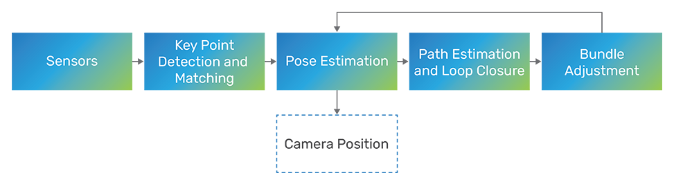
Figure 4 shows a generalized flow of SLAM. Each of the blocks is based on a classical computer vision (CV) approach. However, they rely heavily on a variety of linear algebra and matrix operations, so they are computationally heavy, and can be implemented on a CPU or GPU.
Using a CPU is ideal for general-purpose usage and prototyping, but it has limited performance capabilities. One limitation is a small number of SIMD lanes for parallel processing. In addition, it is not power efficient, so it’s not the best option to scale, and, in some cases, may not be able to deliver SLAM performance in real time.
Using a GPU is the next level up, in terms of computational ability. It has a variety of modalities for parallel processing, which can help achieve great performance and to meet real-time requirements. But again, GPUs are also power hungry and generate a lot of heat. Additionally, SoC vendors cannot justify adding the real estate needed for a GPU in their floorplan just to do processing in this way.
This is where a specialized DSP comes in. DSPs are highly programmable and require a small area, making them scalable for mass deployment in devices of various markets.
Tensilica Vision Q7 DSP
The Cadence Tensilica Vision Q7 DSP is designed from the ground up to enable high-performance SLAM on the edge and in other devices. The Vision Q7 DSP is the sixth generation of vision and AI DSPs from the Tensilica family. Cadence has optimized instructions for faster performance on matrix operations, feature extraction, and convolutions to give the best performance yet on vision DSPs, providing the perfect balance of high performance and low power that is essential to SLAM applications at the edge. It can deliver up to 2X greater performance for vision and AI in the same area compared to its predecessor, the Tensilica Vision Q6 DSP.
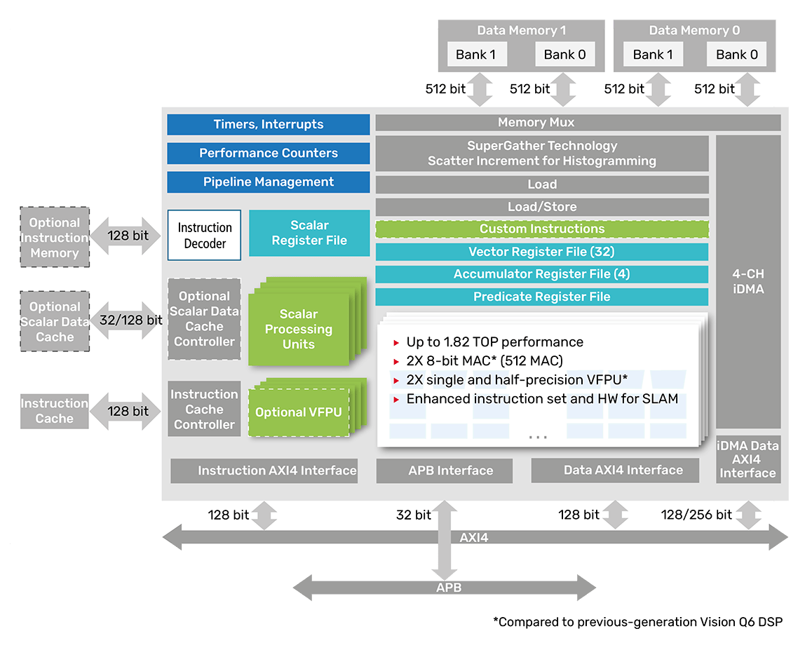
As shown in Figure 5, the Tensilica Vision Q7 DSP offers the following high-level features:
- 512 MAC (8-bit) processing
- 64-way SIMD VLIW processor
- 1024-bit memory interface with dual load and store
- 2X vector floating point unit (vFPU) processing compared to previous DSPs
- Integrated 3D DMA with four channels
- Optional packages to accelerate SLAM performance
- Delivering up to 2 tera-operations per second (TOPS)
Additionally, the Tensilica Vision Q7 DSP is designed for ISO 26262 certification, making it a great candidate for automotive applications. Figure 6 illustrates a typical architecture with a variety of sensors connected to the Vision Q7 DSP for the purposes of computing SLAM.
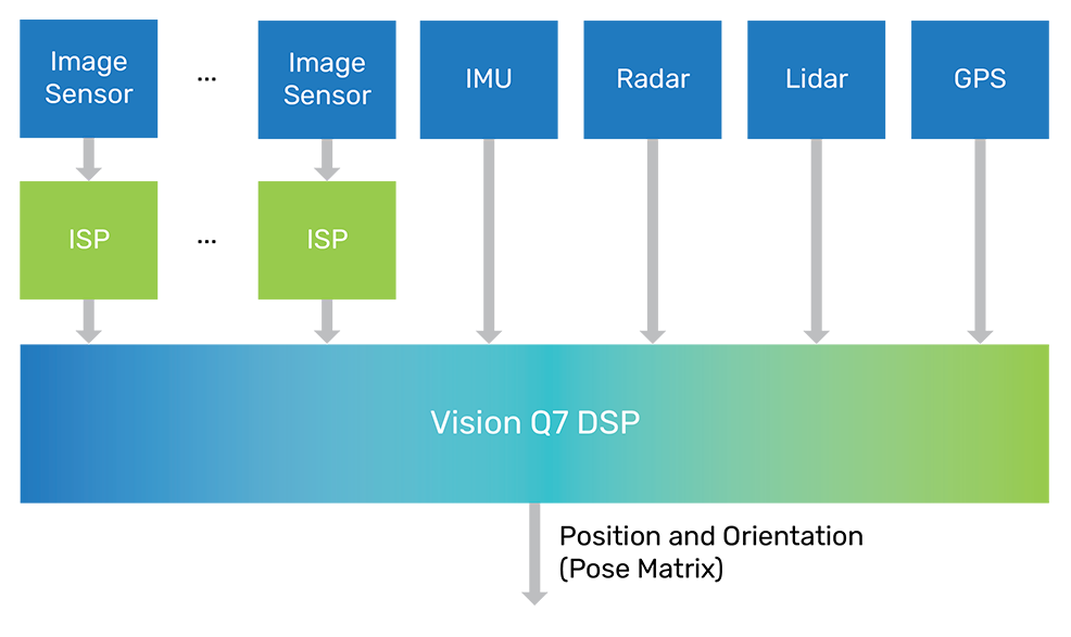
Additionally, the Vision Q7 DSP can also enable many decentralized and distributed systems, whereby the DSP can be placed near the sensors themselves in order to process the data before it arrives at the CPU, thereby reducing the memory bandwidth and data that needs to be transmitted. This approach is most commonly used in a complicated system like a vehicle to meet the needs of safety-critical and high-performance next-generation applications.
Ease of development and tools
In addition to being fully supported in the Cadence Tensilica Xtensa® Xplorer development environment, the Vision Q7 DSP also leverages the mature and highly optimized Xtensa Imaging Library. Inspired by OpenCV (the C++ computer vision library), Cadence has ported many of the OpenCV functions, maintaining similar function names and API, so transitioning from OpenCV is straightforward.
The Vision Q7 DSP is supported by the Tensilica Neural Network compiler. The Tensilica Neural Network compiler maps neural networks into executable and highly optimized high-performance code for the Vision Q7 DSP, leveraging a comprehensive set of optimized neural network library functions.
Performance comparison
Cadence has performed an in-house implementation of VSLAM using a single camera input and profiled the various blocks of the SLAM pipeline on both the Vision Q7 DSP and its predecessor, the Vision Q6 DSP (see Figure 7).

The Vision Q7 DSP shows a close to 2X performance gain over the Vision Q6 DSP in various blocks of the SLAM pipeline. Improved instructions, optimized packages, and more MACs result in higher frequency for estimating camera position, and, furthermore, a better experience when the Vision Q7 DSP is used to accelerate SLAM-based applications. While providing this performance gain, the Vision Q7 DSP also requires the same area as the Vision Q6 DSP and consumes less power, making it an ideal platform for future products.
Conclusion
In this introduction to SLAM, we’ve walked through the implementation of Tensilica Vision DSPs targeting automotive usages, with a focus on purely computer vision approaches to implement a SLAM workflow. We have also shown a comparison between the Vision Q7 DSP and its predecessor, the Vision Q6 DSP, and the improvements in performance in the various blocks.
Recent advances have been made by integrating various convolutional neural network (CNN) layers to enhance the key point matching and feature extraction stage amongst other building blocks. The Tensilica Q7 DSP supports many layers required by the latest neural networks, making this type of fusion between vision and AI possible on the same DSP. This type of harmonious marriage between vision processing and AI is key to bringing forth the next generation of SLAM-based applications to the automotive market.
References
- A. Bhutani and P. Wadhwani, “SLAM Technology Market size worth over $2bn by 2024,” Global Market Insights, 1 October 2018, [Accessed 1 December 2020].