White Paper
A Faster, More Accurate Approach for System-Level Performance Verification of a Wireless RFIC Design
Wireless RFIC designs are growing more complex, increasing the challenge of verifying system-level performance. Designers are expected to be experts on a variety of ever-changing wireless standards and protocols. They must also contend with time-consuming manual simulation setup and post-processing of the simulation results. This paper discusses how an advanced simulation methodology, involving characterization and modeling of a RFIC design, enhances both the speed and the accuracy of system-level performance verification of a wireless RFIC.
Overview
Introduction
Are you prepared to not only become an expert in every wireless standard your design supports, but to keep up with each standard’s specifications as it changes? Considering the growing complexity of the chips themselves, along with ever-present time-to-market pressures, can you really afford to engage in time-consuming manual simulation setup and post-processing of the results?
There’s no question that system-level performance verification of mobile designs is critical, given the high expectations on today’s wireless radiofrequency ICs (RFICs) to support many wireless standards and bandwidthintensive applications. However, keeping up to date with wireless standards—whose documentation can span hundreds of pages—is no simple or quick feat.
Large-scale CMOS RFICs supporting modern wireless protocols require verification of IC performance at the RF system level. However, verifying performance at the system level poses challenges. First, it requires different engineering skills and knowledge. The RFIC project team typically consists of an RF system architect and the RF circuit designer. The RF system architect is responsible for interpreting the wireless system specification, defining the system-level architecture, and driving the requirements down to the blocks in the RFIC. The RF circuit designer typically works with traditional circuit specifications, such as gain and noise figure. It has become difficult for the RF circuit designer to verify the performance of the transistor-level design against the wireless system-level performance specification. Second, the sheer complexity of the RFIC makes transistor-level envelope simulation, the traditional common methodology used, computationally very expensive when the number of time samples is large, which is typically the case when modern wireless standards are involved. This complexity can result in hours and even days of verification time.
We will discuss an advanced system-level performance verification approach for wireless RFIC designs that is easier to use, faster, and more accurate than traditional flows in verifying system-level specifications (for example, error vector magnitude (EVM) and adjacent channel power ratio (ACPR)). This verification flow involves:
-
 Performing accurate characterization and modeling of the RF design
 - Applying wireless standard-compliant modulation sources
- Automatically measuring and calculating system-level performance
A Look at Modern Wireless Standards
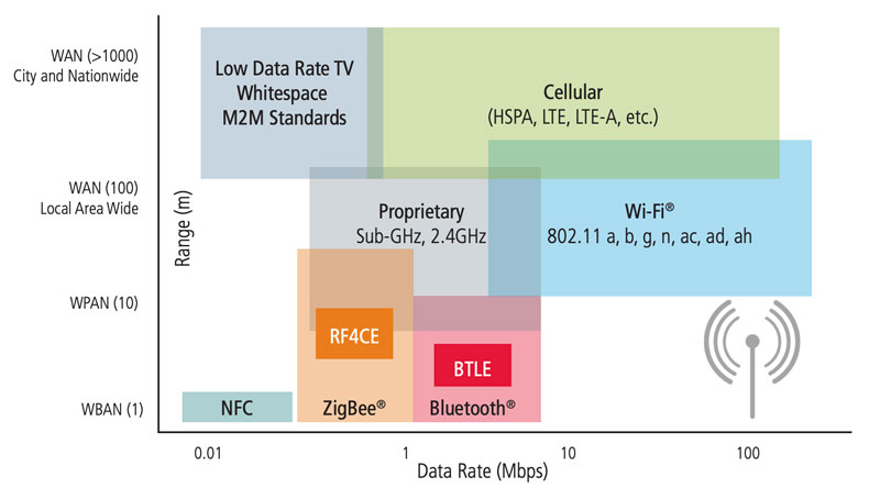
IEEE 802.11, ZigBee, and Long-Term Evolution (LTE) are some of the common, modern wireless standards that RFIC designers are working with today.
IEEE’s 802.11 standard for wireless local area networks (WLANs) provides a basis for wireless network products that use Wi-Fi. This standard covers the 2.4, 3.6, 5, and 60GHz frequency bands. In this family are a series of halfduplex over-the-air modulation techniques that use the same basic protocol1.
The core ZigBee specification, based on the IEEE 802.15.4 standard, is the ZigBee Alliance’s low-cost, low-power mesh network. ZigBee PRO, also developed for low power consumption, supports large networks with thousands of devices. The ZigBee IP specification is, according to the alliance, the first open standard for an IPv6-based full wireless mesh networking solution, providing seamless Internet connections to control low-power, low-cost devices. ZigBee IP will support the forthcoming ZigBee Smart Energy version 2 standard. Finally, ZigBee RF4CE was designed for simple, two-way device-to-device control applications. Such control applications don’t need the full-featured mesh networking capabilities available in the ZigBee specification2.
Developed by 3GPP, the LTE standard guides wireless communication of high-speed data for mobile devices. LTE Advanced provides a standard for even higher data capacity, supporting more simultaneously active subscribers and delivering better performance at cell edges3. Figure 1 shows the wireless landscape.
Why Traditional Performance Verification Falls Short for RFICs
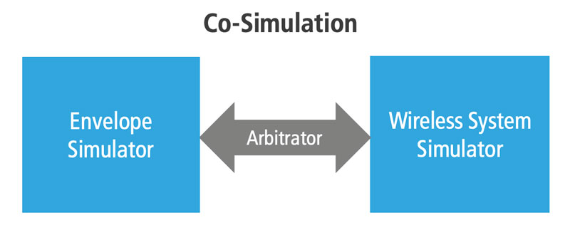
As outlined in Figure 2, a traditional transistor-level performance verification flow typically involves three key components: a wireless system-level simulator (the modulation source), an envelope simulator, and an arbitrator that uses inter-process communication (IPC) to actively connect the two simulator environments, a process also referred to as co-simulation. The arbitrator collects data from the wireless simulator and passes the data on to the envelope simulator and vice versa, during the envelope simulation. In addition, the flow requires engineers to be very familiar with each standard supported—the standards must be translated into parameters to set up and control the simulations. For example, if the design under test (DUT) uses the IEEE 802.11 standard, the designer would need to read through the documentation to extract the required frequency parameters, such as the fundamental frequency, step period, and frequency of resolution. Then, the designer would need to manually set up and drive the simulation. This approach of using IPC to perform the simulation is inherently inefficient, requiring considerable compute resources. It is also error prone and time consuming.
From a methodology standpoint, in envelope simulation, there are basically two ways to simulate. The engineer can choose to use the wireless simulator and generate an input, run one period of the carrier, move to a later point in time, and repeat the process. When evaluating one period, the simulator can remain at the transistor level (standard envelope) and perform harmonic balance analysis at each time interval, a process suitable for RF modules but not for large-scale RFICs. Alternatively, the engineer can choose to characterize the circuit before the first period, build a behavioral model, and run this behavioral model through the time intervals. This method is considerably faster and is suitable for large-scale RFICs.
Many RFIC design teams opt to use more ad-hoc approaches and/or verification tools from multiple vendors to ensure that the RF system performance parameters are met and supported by the RF block design in the RFIC. When doing so, these engineers must make sure these disparate tools will work together, become proficient in multiple tools and environments, and deal with several tool vendors.
The trend now is toward building RF circuits, like transmitters, using CMOS process technology because transistors are relatively inexpensive. For larger scale CMOS RFICs, where the volume of simulation data is far greater, the traditional RFIC simulation methodology is not adequate. A new approach is needed to efficiently move the design from the implementation flow into the simulation flow and to verify the design quickly and accurately.
How Can Performance Verification Be Improved?
One novel way to efficiently evaluate the system-level performance of a wireless RFIC involves these steps:
- Perform accurate characterization and modeling of the RF design
- Apply wireless standard-compliant modulation sources
- Automatically measure the output to calculate system-level performance, including EVM, spectrum, ACPR, and bit error rate (BER) measurements.
Figure 3 illustrates the new methodology, available in a single design environment and in a single kernel and simulation engine.
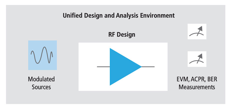
As a first step in this streamlined approach, the circuit is characterized via large signal analysis (harmonic balance). Next, based on this series of harmonic balance analyses, a behavioral model is built. Then, the time evaluations start. The behavioral model is used to evaluate the circuit at each time interval—a much faster approach than performing a full harmonic balance analysis at each interval.
In choosing technology that accomplishes the above steps, some capabilities worthy of consideration include:
- Automation—The ability to automatically add a wireless standard-compliant modulated source and perform the simulation set-up would shave weeks, or even months, off system performance verification
- Fast performance—Technology that is hundreds of times faster than traditional transistor-level envelope analysis can result in verification time of minutes versus days
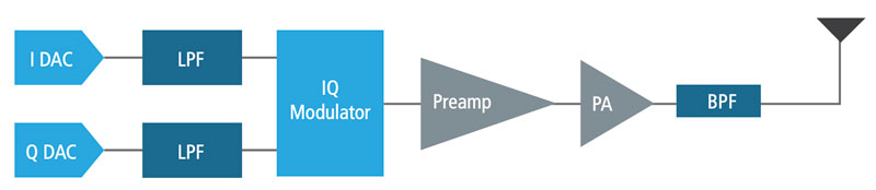
- Modeling technology—The ability to automatically and accurately characterize the DUT, that is, the blocks of the design, can be very beneficial. For example, for an LTE wireless base station transmitter design, as diagrammed in Figure 4, imagine the advantages of being able to characterize the power amplifier, or the modulators, or both together.
- Post-processing—Calculating system parameters (EVM, ACPR, BER) and visualizing the associated waveforms requires intimate knowledge of each wireless communication standard. Technology that automates this process can save time and boost accuracy of the calculations.
Advanced, Automated Wireless RFIC System-Level Performance Verification Methodology
Cadence provides an advanced wireless RFIC verification methodology that delivers high performance and accuracy, with powerful modeling technology and integration with the post-simulation manufacturing flow. The methodology is based on two integrated tools, Spectre RF Simulation Option and Virtuoso Analog Design Environment.
Spectre RF wireless analysis delivers a significant productivity boost that makes more robust verification possible. It supports modern wireless standards, including the IEEE 802.11 family, LTE, LTE-A, ZigBee, and 802.15.4g (smart meter). Its single-kernel fast envelope simulation engine is a key contributor to the tool’s fast system-level performance verification, along with the modeling technology that makes it inherently more efficient versus multiple engines. A modulated wireless standard-compliant source provides the input to the DUT. The modulated sources are available as library components in the Virtuoso Analog Design Environment. They are fully parameterized according to the specification of the wireless protocol selected, which makes the simulation set up and control tasks much easier.
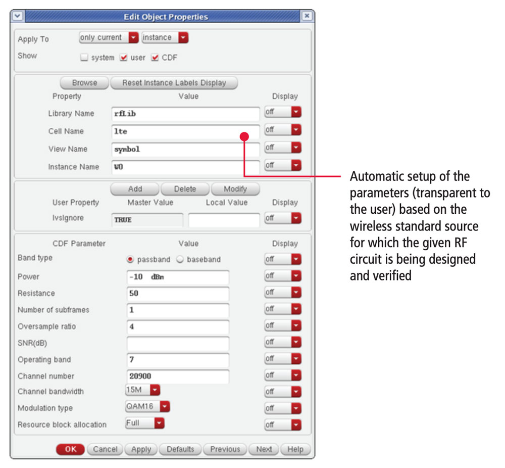
Specifically, with the Virtuoso Analog Design Environment GUI, the designer can select a given wireless modulated source from the RF library catalog and the associated symbol schematic. The simulation engine automatically sets up simulation parameters—sampling rates, stop times, strobe options, and carrier frequencies—based on standard signal sources. With this automated simulation control, the designer can avoid common setup mistakes that can affect simulation and measurement accuracy.
The fast envelope simulation engine characterizes and creates an accurate model of the DUT, providing 100X to 1,000X faster simulation than the traditional transistor-level envelope simulation methods.
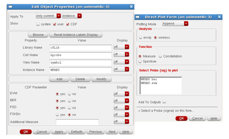
The Spectre RF tool performs automated standard-specific post-processing at runtime. The designer can simply instantiate the wprobe (wireless probe) on the schematic at the outputs of interest, such as the output of the PA or the modulator of Figure 4. The EVM-related parameters (time steps, carrier frequencies, and stop times) are automatically propagated and calculated by the Spectre RF tool. Figure 6 shows the simple user interface for evaluating RFIC system-level specifications.
The native access and integration of the Spectre RF Simulation Option with the Virtuoso Analog Design Environment provide capabilities for automated regression simulation and data processing. To help users analyze the results, the Virtuoso Analog Design Environment provides plots depicting constellation and ACPR, key measurements of distortion, and its impact on system-level performance, for the RF architect and RF circuit designer. With this RFIC performance verification flow, designers no longer need to rely on a multiple-vendor tool flow or on a third-party tool. Instead, they get a complete single-kernel simulation engine flow supported by the OpenAccess database, from design entry to final verification. They don’t have to worry about errors in translation that can crop up with disparate systems, and they can feel assured that implementation and design processes are synchronized.

Summary
The growing complexity of wireless RFIC designs is rendering traditional system-level performance verification methodologies ineffective. Moreover, it’s impractical for RF design engineers to become proficient in all of the detailed, continually evolving wireless communication standards that their designs are targeted to support. By moving to an automated system-level performance verification flow, engineers can benefit from higher accuracy and faster simulation without having to wade through hundreds of pages detailing wireless standard specifications. The Cadence Spectre RF Simulation Option and Virtuoso Analog Design Environment provide an advanced, integrated flow that automates performance verification, giving the RF circuit designer assurance that the IC will deliver the RF system performance required.
For Further Information
Learn more about Spectre RF Simulation Option
Learn more about Virtuoso Analog Design Environment