White Paper
Tensilica DSP Code Generation Toolbox with MATLAB/Simulink
MATLAB and Simulink are widely used for modeling and simulating real-time dynamical systems. To verify the performance of MATLAB/Simulink models of these systems in a real-time application, MATLAB/Simulink models are converted to embedded C code and executed on a target processor or its equivalent Instruction Set Simulator (ISS). To deploy the generated C code in a processor, the generated code is optimized, compiled, downloaded, and run on a processor or ISS. To enable this, a Hardware Support Package (HSP), which is a set of tools to help with the process, is provided. This paper describes the features of the HSP developed for the Cadence Tensilica ConnX B10 and B20 processors and presents an example performance report obtained using the HSP for the ConnX B10 processor.
Overview
Introduction
MATLAB and Simulink are popular programming environments for algorithm development. MATLAB is a multi-paradigm programming language and numeric computing environment used for matrix manipulations, plotting functions, and data, implementing algorithms, creating user interfaces, and interfacing with programs written in other languages [1]. Simulink is a MATLAB-based graphical programming environment for modeling, simulating, and analyzing multidomain dynamical systems [2].
Often, the MATLAB script or Simulink model must be implemented on a processor to verify its performance for a real-time application. For this, the MATLAB script or Simulink model has to be converted to C code to deploy on a processor. Manual conversion to C code is tedious and could introduce manual coding errors.
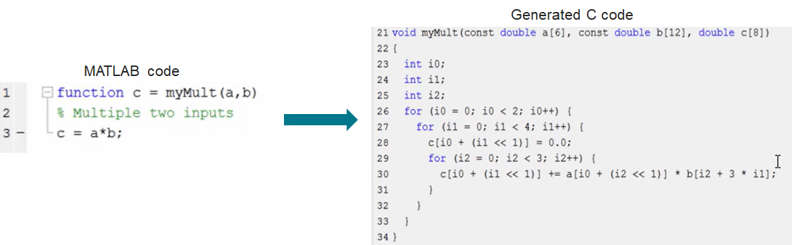
MATLAB provides MATLAB Coder and Embedded Coder tools for automatic C code generation. Figure 1 shows the sample conversion of a MATLAB script to C code done by MATLAB Coder. This generated code can be integrated into projects as source code, static libraries, dynamic libraries, or even as standalone executables.
To deploy the generated C code on a processor, the generated code must be compiled, downloaded, and executed on a processor or the processor’s Instruction Set Simulator (ISS). The functional verification of the execution, i.e., checking the similarity of the outputs between MATLAB/Simulink and the processor/ISS, can also be performed. Additionally, the cycle performance measurement, i.e., the number of cycles taken to run the code on the processor/ISS, can be done.
A Hardware Support Package (HSP) that provides supporting tools is developed to aid in the above requirements. This package enables the rapid prototyping of MATLAB/Simulink models on Tensilica DSPs.
This paper explains the features of the HSP for Tensilica ConnX DSPs. The HSP enables users to generate, optimize, build, execute and verify code from MATLAB and Simulink on Tensilica ConnX B10 and B20 processors [3]. It includes Tensilica Xtensa tools and a code replacement library. This support package can be used for rapid prototyping and production workflows for different control applications.
The following sections discuss the prerequisite concepts for HSP, namely, Code Replacement Library (CRL) and Processor-Inthe-Loop (PIL) execution. Also, the user must have MATLAB, MATLAB Coder, and Embedded Coder toolboxes provided by Mathworks. In addition, Simulink and Simulink Coder toolboxes are required to generate code from Simulink.
Code Replacement Library
Code replacement is a technique to change the code generated by MATLAB Coder for functions and operators with platformspecific custom functions. MATLAB provides this standard technique via MATLAB/Embedded/Simulink Coder tools. For example, as provided on the Mathworks website [4], MATLAB/Embedded/Simulink Coder can replace the generated code for the following operations:
-
 Optimization for a specific run-time environment, including, but not limited to, specific target hardware
 - Integration with existing application code
- Compliance with a standard, such as AUTomotive Open System ARchitecture (AUTOSAR)
- Modification of code behavior, such as enabling or disabling non-finite or inline support
- Application- or project-specific code requirements, such as:
- Elimination of math.h
- Elimination of system header files
- Elimination of calls to memcpy() or memset()
- Use of Basic Linear Algebra Subprograms (BLAS)
- Use of a specific BLAS
-
The toolbox supports two types of optimization in generated code:
- Using Code Replacement Library (CRL). The details of the CRL technique are explained in this section
- Auto-vectorization by Xtensa compiler. For more information on auto-vectorization, please refer to the Xtensa XT-CLANG Compiler User’s Guide [5]
The remainder of this section explains the CRL optimization method.
The toolbox supports the following two types of CRLs:
Native CRL
A Native code replacement library consists of one or more code replacement tables that specify application-specific implementations of functions and operators. For example, a library for a specific embedded processor specifies function and operator replacements that optimize generated code for that processor. A code replacement table contains one or more code replacement entries, with each entry representing a potential replacement for a function or operator. Each entry maps a conceptual representation of a function or operator to an implementation representation [4]. MATLAB Coder automatically replaces the conceptual representation with the implementation representation.
The implementation representation is based on the ConnX B10 and B20 NatureDSP (NDSP) Libraries. Hence a pre-built ConnX B10, B20 NDSP library is required. Table 1 lists the Native CRL functions supported as part of the package. Currently, only math functions (both scalar and vector variants) are provided in the package. Fixed-point 16-bit, 32-bit and floating-point half, single precision datatypes are supported.
| abs | acos | asin | atan | atan2 | ceil | cos | cosh |
|---|---|---|---|---|---|---|---|
| cot | floor | fmod | ldexp | log10 | log2 | log | pow |
| reciprocal | rsqrt | sin | sinh | sqrt | tan | tanh | exp |
Table 1: Math functions supported by Native CRL
Custom CRL
Custom CRLs integrate NDSP library code with the generated code--they are used to call NDSP function Application Programming Interface (API)) directly. The custom CRL script/block calls the appropriate NDSP library API based on the data arrangement, datatype, complexity (real/complex), and input size. Unlike in the case of Native CRLs, no replacement occurs. Instead, we directly call the NDSP function API. Here also, a pre-built B10 or B20 NDSP library is required. Table 2 lists the Custom CRL functions and the datatypes supported as part of the HSP.
A provision is provided to add the user’s custom CRL and Cadence NDSP-based custom CRL.
| Category | Type | Datatype | ||||
|---|---|---|---|---|---|---|
| int16 | int32 | half | single | double | ||
| FIR Correlation | Linear | Yes | Yes | |||
| Circular | Yes | Yes | ||||
| FIR filtering* | Complex Impulse Response and complex input | Yes | Yes | |||
| FFT | Data arrangements supported by library | Yes | Yes | Yes | Yes | |
| Data arrangements supported by library | Yes | Yes | Yes | Yes | ||
| Data arrangements supported by library | Yes | Yes | Yes | Yes | ||
| Decomposition | Data arrangements supported by library | Yes | Yes | |||
| Data arrangements supported by library | Yes | Yes | ||||
| Data arrangements supported by library | Yes | Yes | ||||
| Data arrangements supported by library | Yes | Yes | ||||
| Matrix Multiplication | Data arrangements supported by library | Yes | Yes | Yes | Yes | |
| Data arrangements supported by library | Yes | Yes | Yes | Yes | ||
* supported only for complex
Table 2: List of Custom CRL functions supported (supported for both real and complex)
Processor-In-the-Loop (PIL) Simulation
Processor-In-the-Loop Simulation is used to deploy the generated C code on a processor. The PIL Simulation’s generated code is compiled, downloaded, and executed on an Instruction Set Simulator (ISS). The functional verification of the execution, i.e., checking the similarity of the outputs between MATLAB/Simulink and the ISS, can also be performed. Additionally, the cycle performance measurement, i.e., the number of cycles taken to run the code on the processor/ISS, can be done [6]. Figure 2 shows a typical PIL execution flow.
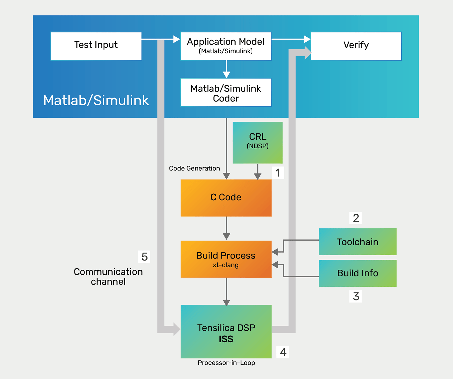
MATLAB/Simulink sends its inputs to the ISS and receives the outputs back. The communication happens over TCP/IP. The processor executes the PIL algorithm when the ISS receives signals from MATLAB/Simulink. The PIL algorithm returns output signals calculated during this step to MATLAB/Simulink through the TCP/IP communication channel.
With PIL simulation, the user can:
- Test whether the model and generated code are numerically equivalent, i.e., functional verification
- Perform code execution profiling, i.e., measure the performance in terms of execution cycles
- Observe code coverage
Hardware Support Package
The Hardware Support Package enables users to generate, optimize, build, execute and verify code, from MATLAB and Simulink, on Tensilica ConnX B10 and B20 processors. The toolbox supports Windows and Linux Operating Systems and can be used for rapid prototyping and production workflows for different control applications. The HSP provides the following features:
- Processor-In-the Loop (PIL) enables the user to:
- Compare MATLAB/Simulink Simulation results with the results on the Tensilica processor/ISS
- Evaluate execution time of algorithms on the specified processor, i.e., code execution profiling
-
- Replace standard Simulink blocks with Cadence IP blocks – Native and Custom CRLs are used for this
- Specify compiler, linker, assembler, and archiver toolchains
- Communicate over a TCP/IP channel between MATLAB/Simulink and target processor ISS
Code Execution Profiling
Users can configure a PIL simulation to produce execution-time metrics for tasks and functions in the generated code. The software calculates execution times from data obtained through code instrumentation added to the PIL application or the generated code under test. The user can use the execution-time metrics to determine whether the generated code meets the requirements for real-time deployment on the target hardware.
Example
The following is an example of a time-to-frequency domain conversion. Figure 3 shows the example Simulink model for timeto-frequency domain conversion.
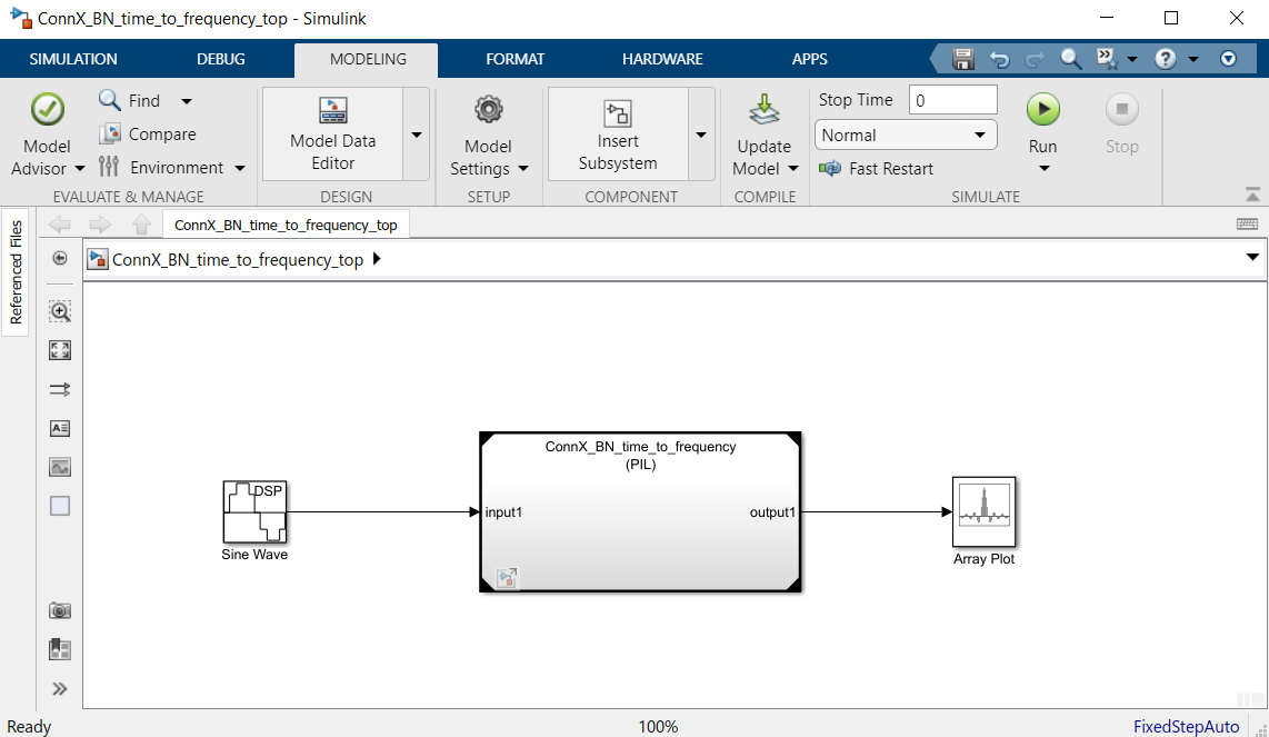
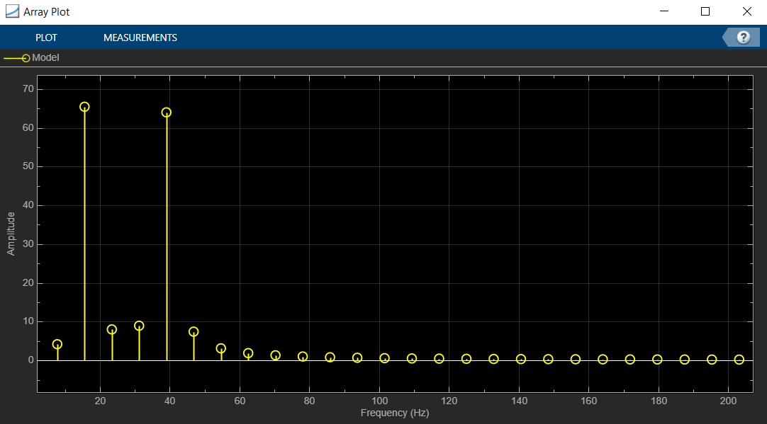
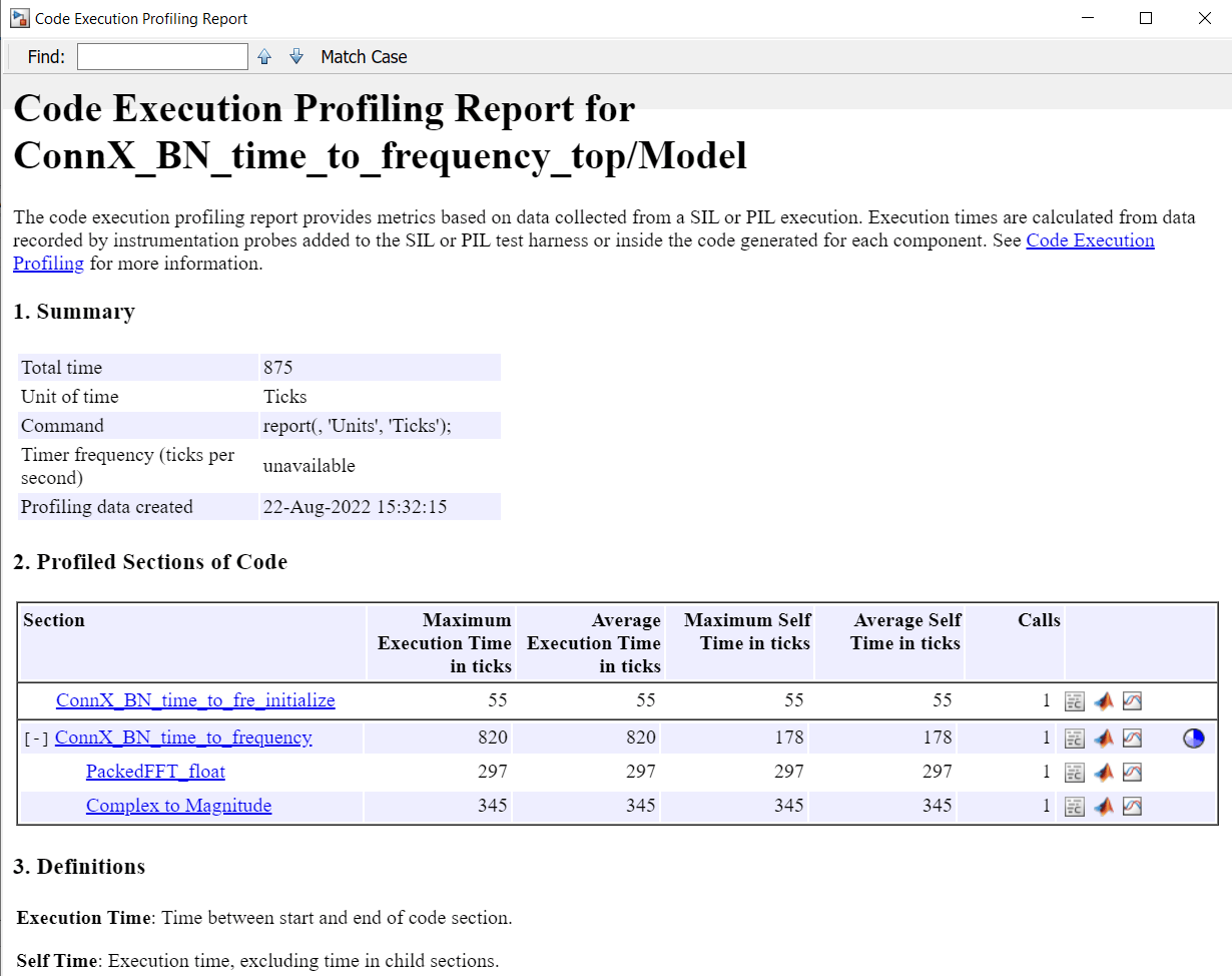
In this model, the time-to-frequency domain conversion part is performed in a referenced model named “ConnX_BN_time_ to_frequency”. This model is run in PIL mode, i.e., it will be converted to C code, compiled, and executed on the ConnX B10 ISS. The rest of the model will execute in Simulink. For every time step, input data is read from a Sine wave generator block (which produces and adds two sinusoids, one with a frequency of 15Hz and the other at 40Hz) and sent to the referenced model block. Simulink displays the results of the time-to-frequency domain conversion.
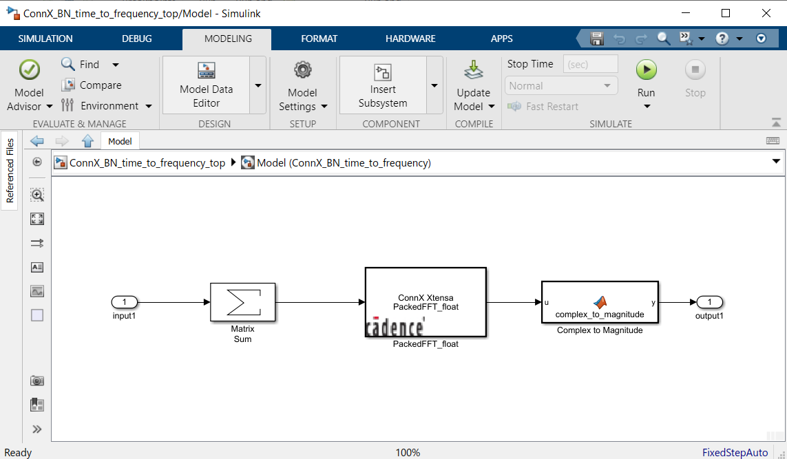
The reference model, in Figure 4, uses a custom CRL block called “PackedFFT_float”. The block is used to compute Fast Fourier Transform (FFT). The custom CRL “PackedFFT_float” is used as the input of a single signal array and floating-point datatype.
Performance
The frequency spectrum of the signal is plotted in Figure 5. As shown, there are peaks at 15Hz and 40Hz, which are the frequencies present in the input signal. Figure 6 shows the code execution profiling report.
Summary
This paper presents the features of the Hardware Support Package for Cadence Tensilica ConnX B10 and B20 processors. These features enable users to generate, optimize, build, execute and verify code from MATLAB and Simulink on the ConnX B10 and B20 processors or their equivalent ISS. Performance results show that the HSP helps in optimizing the code generated from the code generator, for the ConnX B10 processor. Hence, the Cadence-provided HSP toolbox enables rapid prototyping of the MATLAB/Simulink models on Tensilica ConnX DSPs.
Additional Information
For additional information, the user can refer to the user guide of the Matlab/Simulink Code Generation Toolbox for Cadence Tensilica ConnX B10 and B20 processors [7].
References
- Wikipedia - MATLAB
- Simulink
- ConnX B10/B20
- What Is Code Replacement?
- Xtensa XT-CLANG Compilers User’s Guide, Cadence Design Systems
- SIL and PIL Simulations
- Matlab/Simulink Code Generation Toolbox User’s Guide