Technical Brief
Xtensa Processors for Functional Safety Applications with Full ASIL-D Compliance
Cadence Tensilica Xtensa Processors with FlexLock are now certified for full Automotive Safety Integrity Level D (ASIL-D) compliance, with both ASIL-D systematic and ASIL-D random fault protection for use in Functional Safety (FuSa) applications. Tensilica processors are independently certified in accordance to ISO 26262:2018, and are customizable through the Tensilica Instruction Extension (TIE) language to tailor each core optimally for customer products and applications. The products range from simple embedded controllers to high-performance DSPs, each with the option of FlexLock, and offer the most customization of ASIL-D-certified processors available. This enhanced product offering is in addition to processor configurations certified to ASIL-B, providing customers with options to meet their product requirement with the right performance and safety level.
Overview
Introduction
As technology becomes more pervasive in our daily lives and become more autonomous and semi-autonomous in operation, it is critical that systems be trusted to operate safely and minimize the chance of causing harm. FuSa is a specialized engineering discipline that focuses on keeping system failures from causing unsafe behaviors through active detection and either correction or mitigation. The international standard ISO 26262: Road Vehicles is an adaptation of the FuSa standard IEC 61508 for automotive markets and provides a set of guidelines for FuSa engineers to manage safety at all levels through the development of a vehicle. This standard is the basis for FuSa-certified Tensilica Processor IP products from Cadence. Applications outside of automotive may rely on industry- or application-specific standards similarly derived from IEC 61508 for specific environments and use cases.
The ISO 26262 standard defines the criteria used to judge the quality of the FuSa processes followed, as well as quantitative criteria for protection against random faults. These criteria range from ASIL-A (the least safety-critical) to ASIL-D (the most safety-critical and requiring the most exhaustive development process and fault protection).
Cadence’s FuSa Tensilica products are certified by independent third-party auditors for use across all automotive safety integrity levels, from ASIL-A to ASIL-D, and our applications engineering specialists are on hand to support customers with our FuSa deliverables. With components such as processor IP, the usage is not fully known and therefore is certified as a safety element out of context (SEooC), to be tailored to your product and use cases, and eventually the final system. Included with the certified products are the FuSa certificate and collateral needed to assist your own certification. The process begins with a Development Interface Agreement (DIA) outlining the work products, ownership, and plans. Please reach out to Cadence for more information or to get started.
FuSa Product Integration
Implementing a FuSa-certified product requires a deep level of collaboration across system components, including between SoC developers and IP developers, to gain and share insights into failures modes and the mitigation mechanisms that prevent safety failures leading to potential harm. Cadence is committed to enabling FuSa applications across our Tensilica processor lineup, whether it’s an off-the-shelf core configuration directly from Cadence, or one that a customer has optimized for their specific application. For products in the automotive space, ISO 26262 defines the safety process that is needed. The SoC architecture must be defined in a way the meets the safety goals of the final product(s), satisfies the ASIL required, provisions how the internal and external subsystems will be structured and what components are used, and implements the safety mechanisms to achieve the necessary fault metrics.
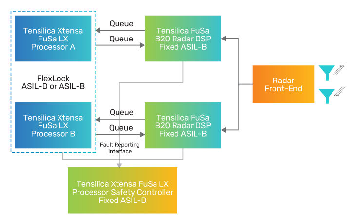
Let’s consider an example of an automotive radar module that contains an SoC comprised of multiple processing elements such as a controller CPU and one or more offload DSPs. The offload DSPs here are processing the radar cube through the radar front-end, and further signal processing of the computed point cloud for object-/lane-detection. If certain patterns are identified, then automated actions (e.g., speed change, braking, avoidance) and user notification (e.g., alert chime, vibration) are triggered.
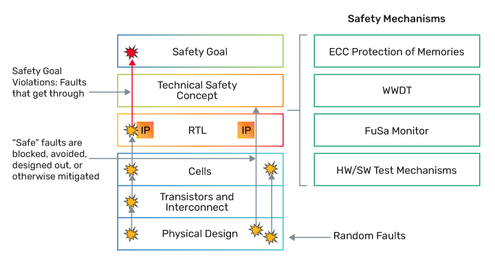
The transistors in the SoC can be subject to random faults. These faults could be permanent, as in the case of a transistor or other physical element wearing out and becoming stuck at a logic “0” or “1”; they could be due to a static fault induced by an alpha particle causing a memory bit to flip from a “0” to a “1”; or they could be transient in nature, caused perhaps by signal crosstalk or some other unexpected noise in the SoC. Whatever their cause, the faults can occur in the processing element in either the logic gates or the memories tightly coupled to the processor.
The system designer could set a safety goal that a random fault in the DSP must not result in a failed detection of an object such as a lane marker. This safety goal would then guide the designer to implement the appropriate safety mechanisms such that if random faults are detected, then the safety controller is notified and can take action such as reinitializing the DSP. If the DSP is already engaged in processing, then the safety controller is responsible to take steps to ensure a safe state is reached before/while the DSP is reinitializing.
The safety controller is in a “safety island” in such a design and will be counted on to make some safety-critical decisions. And, of course, the controller can be subject to random faults as well. Such a fault could have serious consequences if, in the above example, the DSP fault is detected by the controller but it takes an incorrect action in response to it, leaving the system in an unsafe state. In such systems, it is a common practice to use two controllers, each running in lockstep, to add a layer of redundancy that ensures the probability of such an event occurring is greatly reduced.
Processors, both controllers and DSPs, in an automotive SoC are often licensed from a third-party provider due to the complexity of designing a processor to meet the performance requirements of an automotive application such as radar or lidar processing or object detection. As the processor is often provided to the licensee as a black box, the SoC designer must rely on the vendor to design it in accordance with FuSa management processes and to provide the hardware and software mechanisms to facilitate the level of fault detection required to meet the safety goals of the system. Furthermore, the licensee is also reliant on the software tools, including the compiler toolchain, having been designed and verified utilizing a strict process with FuSa in mind.
Hardware Safety Mechanisms
FuSa is inherently about detecting and then correcting or mitigating faults to ensure safe operation. As such, several configuration options within the Xtensa architecture are available to facilitate this and are supported across Tensilica processors, which are detailed in the hardware safety manual and core user guide:
-
 ECC or parity across memories and critical registers for detection and correction of bit errors
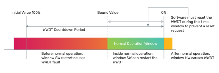
 - Inclusion of a windowed watchdog timer (WWDT) for program sequence monitoring
- Optional FlexLock configuration for dual-core lockstep to provide core logic redundancy
ECC protection on memories provisions for error correction codes to be generated (by hardware) and stored alongside the protected data. When the data is read from memory, the ECC is read with it and compared to a re-calculated code. If the ECC that is read matches the newly calculated ECC, then the data is consumed as normal. If there is a mismatch due to a single bit error the data can be corrected directly on the fly. A 2-bit error, will be detected along with an exception before it is consumed.
Parity offers a simpler protection scheme, whereby a single parity bit is stored as the xor of the written data value. If a single bit error occurs to the data or to the parity bit, then the parity will not match and an exception will be generated. Parity does not protect against multi-bit errors or allow for single-bit correction.
The WWDT is a hardware component that allows the software to monitor the health of the application. Time windows are established based on the specified system behavior, and if the application fails to update the WWDT during the expected time intervals, then a fault will be asserted.
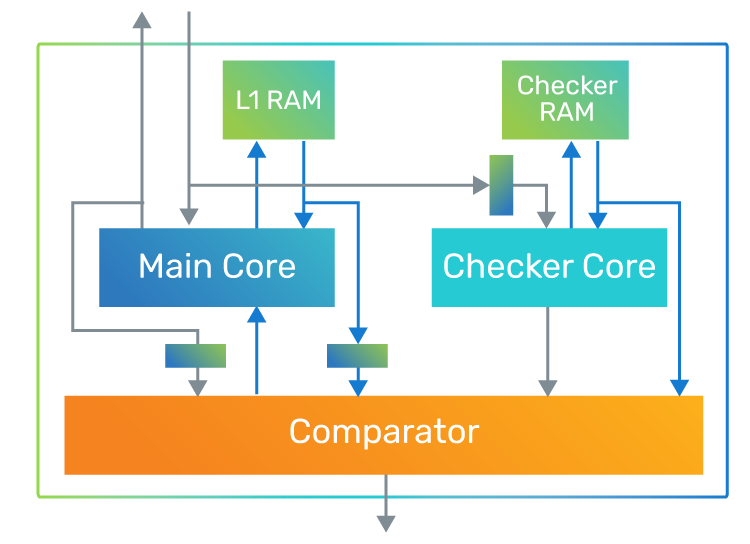
FlexLock is a feature that allows for several options with two physical instantiations of a core configuration:
- FlexLock: All logic and memory for both cores are implemented, and cores may be joined or separated through a controlled reset procedure to change between the lock and split modes of operations. Limitations may be placed on this within the SoC integration if desired.
- Lock mode: Both cores operate in lock-step and execute the same program. The hardware checks that both cores behave identically and if there is a deviation then an exception is asserted. This mode of operation is required for ASIL-D certification of the core as an SEooC.
- Split mode: Cores operate independently from one another and may execute their own separate programs. There are no hardware checks between the cores, and any reciprocal checks between them are left to the application. This mode of operation supports ASIL-B certification of both cores.
-
- Lock-only: A configuration option that restricts the cores to only operate in lock mode and does not allow them to be split. Area is optimized with the removal of all checker core inputs and outputs, as well as the checker core’s L1 memories.
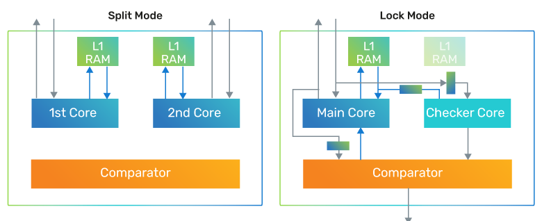
- Memory lock-step: In addition to the FlexLock core configuration, it is possible to configure the memory system to operate in lock mode as well (memory lock-step). When the cores are in lock mode, the local memories for both cores are used, and their outputs are monitored by the comparator. Additionally, when selected along with the lock-only core configuration, the checker core’s L1 memories are instantiated but ECC becomes optional within the FuSa range as redundancy is provided on the RAMs.
Self Test
An important consideration for FuSa is reliability of the hardware platform through the lifetime of the product. Some percentage of test coverage of permanent faults in the hardware that may occur over time can be achieved through software-driven test. Testing that can be performed non-intrusively on the system as part of the FuSa application offers the best frequency of test, though it cannot achieve 100% coverage. To increase fault coverage over the product lifetime, it is possible to have intrusive software and hardware tests as well. These tests must be performed at controlled points in the operation so as to not affect the running safety system, typically after power-up or return from standby.
In order to support the non-intrusive run-time testing of the base processor, a software test library (STL) is available from Cadence with all FuSa cores. STL verifies the correct operation of hardware safety mechanisms, exercising processor logic to facilitate fault detection through execution of self-checking tests on core (base and DSP) functions. STL test subroutines operate in the context of the customer’s running application, callable as ordinary C subroutines with any faults indicated by non-zero return value, unexpected exception, or processor hang. STL tests do not produce exceptions (unless triggered by a fault) or interrupts, load or store outside of the stack or customer-allocated memory buffers, and do not alter the processor state. This allows for STL tests to be run periodically from the application without affecting the run-time behavior of the processor or application.
The STL can be supplemented by customer-specific software tests for the more complete safety subsystem in which the processor is integrated and to cover any custom user TIE that is implemented. Additionally, intrusive software tests can be leveraged to give further coverage, but with the requirement of being performed at controlled points as the processor may need to undergo a reset, or other controlled sequence potentially with a state store/ restore, to resume normal operation.
Hardware test such as Memory BIST (MBIST) and Logic BIST (LBIST) can be a powerful addition to increase fault coverage. These are implemented outside of the core product release and will require a reset and possible state store/restore to resume normal operation.
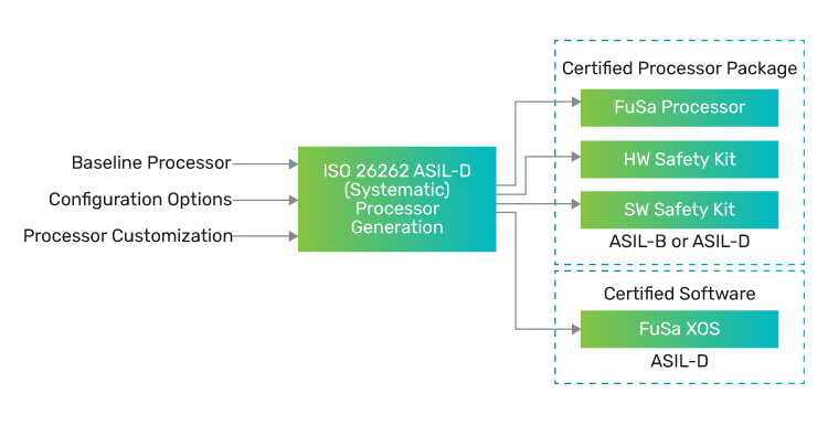
Products
Certified ISO 26262:2018-compliant Tensilica FuSa products all include a comprehensive safety package for hardware and software.
FuSa Processor Hardware Release
FuSa licensees are enabled to request a production hardware release through the Xtensa Processor Generator (XPG) for an ISO 26262-compliant build of their core configuration and user TIE. This configuration will undergo internal checks that all options comply with the FuSa range specified in the hardware safety manual, after which the RTL and software models are released. This build triggers the release of the hardware safety kit.
FuSa Hardware Safety Kit
The FuSa hardware safety kit includes the safety certificate with the appropriate ASIL to which the build is compliant. The certificate is achieved through an independent audit of the Cadence safety process and product releases.
The Hardware Safety Manual presents the relevant safety information for the FuSa Tensilica processor. The Safety Manual outlines the safety lifecycle for the processor as an IP SEooC, as defined in ISO 26262 and details the core configurations within scope of the FuSa product (FuSa range). The licensee is responsible for selection and implementation of appropriate user-implemented safety mechanisms, described in the document, in order to achieve the appropriate random hardware failure safety metrics.
The Failure modes, effects, and diagnostic analysis (FMEDA) provides a detailed analysis of the different failure modes and diagnostic capability for the processor. It is important to note that Cadence provides the IP release in RTL form, and all decisions on RTL synthesis, gate-level netlist, and implementation into silicon are made by the licensee and are outside of Cadence’s scope. The licensee is responsible for the verification of safety metrics by using verification methods (such as fault injection) to prove the fault coverage in the design, and the final quantitative FMEDA is therefore the responsibility of the licensee. The qualitative FMEDA from Cadence provides the mechanisms to input the implementation details to allow the rapid creation of the necessary quantitative analysis.
The hardware verification report provided shows that the core configuration has passed the safety verification tests applicable to the certified release.
FuSa Software Safety Kit
The software safety kit includes a safety certificate showing that included software products are compliant to ASIL-D, designed with the highest quality of FuSa in mind. The certificate is achieved through an independent audit of the Cadence safety process and product releases.
The included software products are the XT-CLANG C/C++ toolchain plus the XTOS, HAL, and iDMA library. There is a safety manual for the toolchain and another for the remaining items.
These software safety manuals contain relevant safety information for the software product developed and pre-qualified to be suitable for use in development of projects up to ASIL-D. They were created to assist developers using a safety-related development process for safety-critical applications to be in accordance with the ASIL-D requirements of ISO 26262 and provide information regarding the FuSa usage of the product.
Additional FuSa Software
In addition to the FuSa software available for all products, the XOS multi-threaded operating system kernel is available in a FuSa-certified release on any FuSa Tensilica cores. For Tensilica Vision processors (P6, Q7, Q8), the Imaging library (XILib) is available as FuSa-certified.
Conclusion
FuSa plays a critical role in automotive products, with a strong need for certified components directly from the component vendor to be used in order to ensure proper conformance to the ISO 26262 safety standard. With the addition of FlexLock, Cadence Tensilica products are now available that meet full ASIL-D compliance for the highest level of safety. Tensilica processor configurations supporting certification to ASIL-B, as well as non-FuSa configurations have been and remain available, providing customers with a wide portfolio of processor options to achieve the performance and FuSa goals for the integrated product.