Technical Brief
Celsius EC Solver
Key Features of Electronics Cooling Software
The Cadence Celsius EC Solver is electronics cooling simulation software for accurate and fast analysis of the thermal performance of electronic systems. It enables electronic system designers to accurately address the most challenging thermal/electronics cooling issues today. The Celsius EC Solver utilizes a powerful computational engine and meshing technology that enables designers to model and analyze complex designs to reduce the risks of product failures and optimize thermal solutions to maximize performance.
Overview
Design Overview
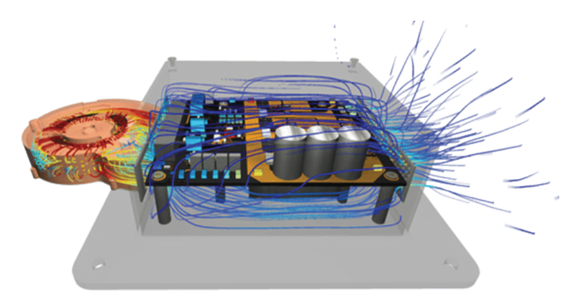
The Celsius EC Solver enables designers to address thermal/ electronics cooling challenges early in the design cycle, reducing the risk of product failure. The software can analyze airflow, temperature, and heat transfer in electronic assemblies and enclosures. It solves for natural convection, forced convection, solar heating, and liquid cooling (Figure 1). As such, it analyzes the fluid flow and heat transfer of even the most complex electronic systems, and it solves for all modes of heat transfer using a proprietary multi-level unstructured (MLUS) meshing technology.
Solid Modeling: Enhanced CAD Import and Editing
The Celsius EC Solver integrated CAD editor provides significant import functionality enhancements by enabling import directly from all major CAD software providers, in addition to existing standards for exchanging product model data (STEP) and initial graphics exchange specifications (IGES) import functionality.
After import, changes can be made directly in the software, enabling users to explore design changes without going back and forth between different platforms. The CAD editor allows users to move, resize, or delete existing features in the geometry, such as holes or pads (Figure 2). Advanced feature detection allows easy selection of key geometry features. Users can move vent holes or change the size or thickness of an enclosure. The CAD editor can also edit solid obstructions created in Celsius EC Solver. Therefore, users can create even more complex shapes directly in the software.
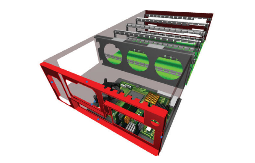
Feature detection simplifies geometry by allowing groups of features, such as small holes or chamfers, to be automatically removed in one step. In addition, parts such as holes and extrusions can be sketched and added to existing CAD parts if additional openings or pads need to be added to evaluate thermal design iterations. Both through and non-through holes and buried holes can all be created.
Thermal Modeling: Expanded 1D Flow Network Capabilities
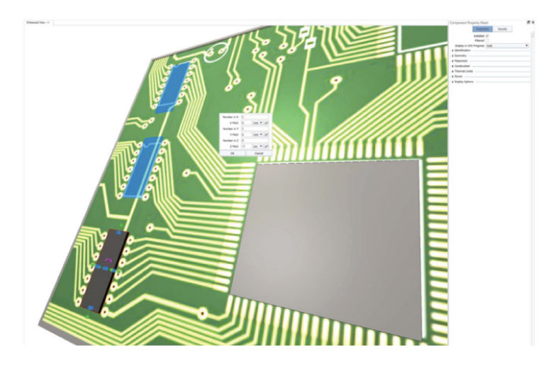
The 1D flow network capabilities provide more component power functionality, including the ability to perform a transient simulation with component power (Figure 3). The co-simulation of connected 1D and 3D models delivers significantly faster performance, enhancing user productivity.

In addition to temperature, users can view results for pressure, pressure drop, volume flow rate, or velocity on pipes and ducts. The legend, pipes, and ducts are colored according to the variables. The progression of flow network solves can be monitored by reviewing the convergence of controller errors, controller outputs, and sensor measurement values. The results tab shows the operating loss coefficients of flow network joins and T-junctions and the operating flow resistance of pipes and ducts when flow resistance is set to auto. Users can specify both secondary and primary flow on a heat exchanger and set derated and rated speeds on a pump or fan.
Use Model: Streamlining Usability
The Celsius EC Solver’s user interface (UI) automatically places intelligent modeling objects within the system-level model, providing automatic object-based mesh generation and determining the ideal grid size for a simulation. Its UI navigation makes the Celsius EC Solver intuitive and easy to use. Invoking the enhanced view, the object picker tool opens a list of all objects under the user’s mouse cursor position, making it easier to select overlapping objects or child objects within their parent. When users hover over a specific property in an object’s property sheet, a tooltip will appear to briefly describe the property and provide important project information.
In addition, the object pattern pop-up dialog enables users to move the model around and see a preview of the pattern before implementing the change (Figure 4). Holding the shift key while using the keyboard shortcuts to change to a 2D view retains the current zoom level of the model.
Users can cycle through eight typical isometric viewing angles in the enhanced view using the “I” keyboard shortcut.
Use Model: Animations and More
Report generation, animations, automation, and more are all part of the Celsius EC Solver user experience. The software makes it easy to filter table columns, which helps users quickly populate their fully customizable report property tables.
Likewise, the object plot and result plane legends are more customizable with legend bins. The number of bins, their boundaries, and the color associated with each bin can also be customized. This feature allows grouping the legends of a specified variable for quicker legend generation. These custom legends are also displayed in reports.
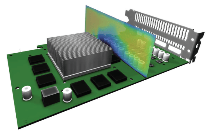
When configuring legends for a report, users can quickly select multiple legends and apply changes to all of them using the select multiple legends window. In addition, maximum and minimum objects and markers can be attached to objects, such as components and solid obstructions, to identify the location and value for a specified variable’s maximum and minimum values on a given object of importance (Figure 5).

Result planes can be fully animated in the enhanced view, which allows the result planes to sweep through the model during an animation (Figure 6).
The measure tool is available in the enhanced view. The snap-to-object is simple, and the measured lines are colored to indicate direction. The option to automatically open reports as Microsoft Word files after they have been generated has been added.
Threshold temperature can be specified on result volumes that calculate the flow results above and below the threshold. This is reported in the result volume and face results tab. In the graphical view, all legend properties have been combined into the legend options window, which enables users to configure legends quickly and easily.
Additional commands like converting solid obstructions to any smart objects, exporting images and videos in the enhanced view, creating versions or alternates, and exporting the version tree to a CSV file, are all part of the Celsius EC Solver offering.
High-Performance Computing: More Power for the User
The process of submitting and solving jobs is made even more powerful with the support of high-performance computing (HPC) within the Celsius EC Solver. A checkpoint feature has been added for solving model data recovery mode. Users can set intervals per iteration or time stamp to save the solving data and recover from the last setpoint if a failure occurs. This feature can save significant time when recovering from an unsuccessful simulation on a large model and works for both steady-state and transient solves.
When submitting jobs to an HPC network, users can choose whether to solve on Windows or Linux nodes if they are available. When the Linux support option is activated, a choice for the solve platform is available in the “solve in queue.” The job priority of a “solve in queue” job can be displayed as a column in the View Queues window.
Using the resistance function property, users can now calculate the pressure drop on perforated obstructions using Reynold’s number-dependent equations for inertial and viscous resistance coefficients. The heat flux magnitude variable units can be set to W/cm2 or W/mm2.
Conclusion
The Celsius EC Solver offers numerous features that enable designers to more quickly and accurately address their thermal/electronics cooling management challenges. CAD import and editing, 1D flow network capabilities, UI modeling, animation, and automation functionality all serve to make the Celsius EC Solver a fast, accurate and efficient solution for helping designers bring their products to market.