Datasheet
Sigrity SPEED2000
Layout-based, time-domain signal integrity/power integrity/electromagnetic interference simulations
Cadence Sigrity SPEED2000 technology provides for direct layout-based, time-domain simulations of an entire board design or for a specific IC package together with the PCB. These simulations can include various SPICE/S-parameter interconnect models and component models commonly used in signal integrity (SI)/power integrity (PI) simulations. The Sigrity SPEED2000 engine combines circuit solver and transmission line solver with a fast electromagnetic (EM) field solver to capture dynamic interactions between signal, power, and ground on signals and planes in one time-domain simulation. Using the tool, you can perform a broad range of workflows for various levels of SI and PI analysis as well as electromagnetic interference (EMI) and electro-static discharge (ESD) studies in a single environment.
Overview
Sigrity SPEED2000 ERC
Electrical rule checking (ERC) is a fast and easy way to scan a full board for first-order electrical design problems without the requirement for IBIS models. These checks fill in the gap between a geometry-based design rules check (DRC) and a simulationbased signoff simulation task performed with IBIS models.
Basic ERC
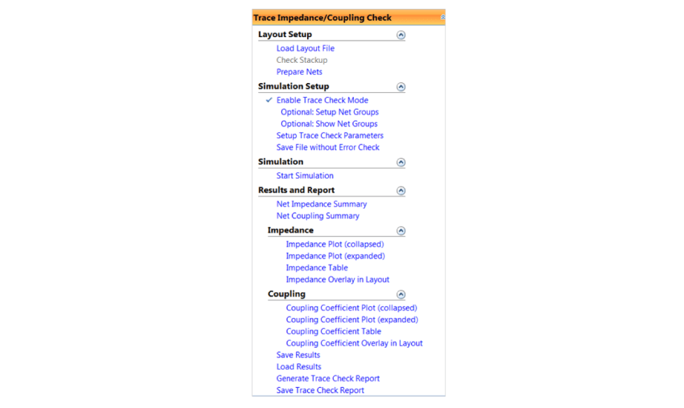
Trace impedance, coupling, and return path discontinuity checks provide a micro view of layout trace properties, which are useful for design and debug. Using this technology, you can quickly screen the board layout to get:
-
 A high-level summary of impedance and coupling results by net, including number of vias, number of return path discontinuities, and number of trace sections over voids, trace lengths, and trace delays
 - Detailed/interactive checks by trace segment, including collapsed and expended plots, layout overlay, and plots to layout over cross-probing
- Both single-ended and differential impedance and coupling
- Violation reports, based on your defined thresholds, will be formatted in tables and can be highlighted in layout
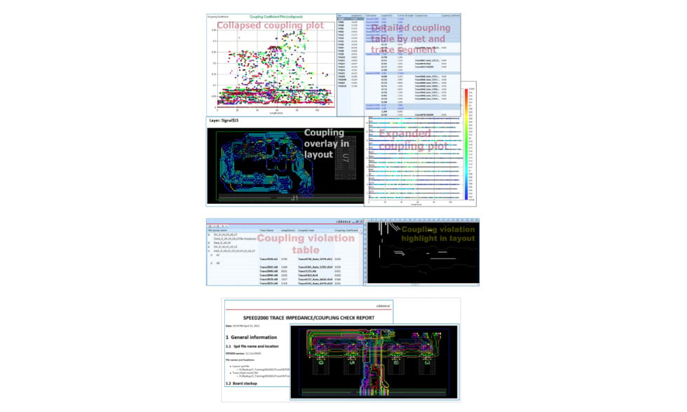
Trace check results are bundled by net groups, making the comparison easy and meaningful. Set up of net groups is easy and automated. Based on the trace check results, you can easily see the impedance/ coupling distribution to identify the violations in the plots, and use cross-probing to locate the violations in the layout. Reports are available in HTML.
Simulation-based ERC
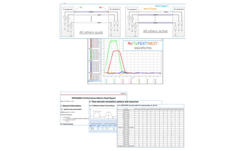
Simulation-based rule checking provides a more detailed view of overall SI performance, which is useful for additional screening and design reviews before moving on to detailed power-aware SI analysis for signoff. Simulation-based electrical rule checks rely on time-domain simulations that consider crosstalk and non-ideal power and ground supplies, without having to assign IBIS models. Save time when checking on a large number of nets with an easy-to-use workflow combined with a high level of automation and parallel computing. Generated results include:
- TX/RX waveforms and worst-case NEXT/FEXT waveforms
- SI performance metrics based on signal magnitudes, inter-symbol interference (ISI) and crosstalk at receivers
- Top 10 crosstalk aggressors
- Extensive checking reports
Simulation-based electrical rule checks can be used in the following cases:
- To screen boards and identify worst cases for further analysis
- To investigate SI impact of design rule violations and tradeoffs
- To compare against a known good design or reference design
Power-aware ERC
When run with a non-ideal PDN, simulation-based rule checking can be expanded to simulate the impact of power noise and the coupling to signals. These expanded checks include:
- Plane ringing that couples to reflections from signal impedance discontinuities
- Plane ringing that couples to signals generating new crosstalk
- Plane ringing that increases crosstalk between coupled signals
- Delay impacted by power or ground plane noise
- Impact of signal vias coupling to power and/or ground planes causing ringing that impacts reflection and crosstalk results
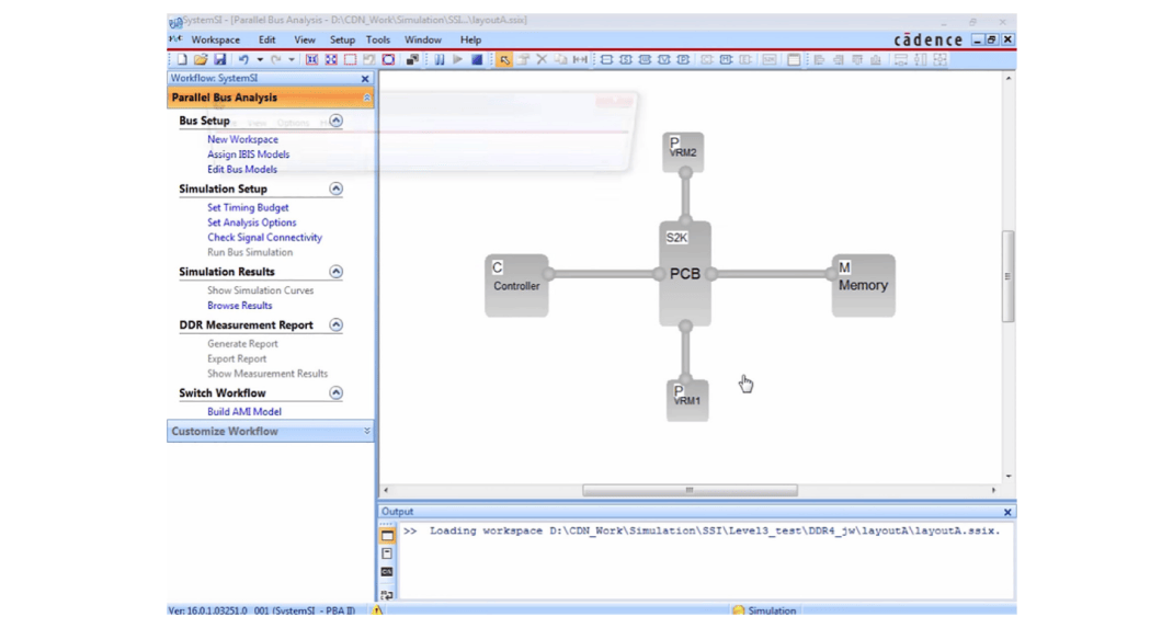
DDR Simulation with Sigrity SPEED2000 and SystemSI Tools
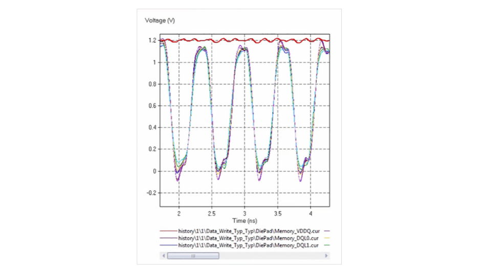
Due to complexities in setting up DDR simulations as well as interpreting the post-simulation results, Cadence recommends driving DDR simulations from the Sigrity SystemSI tool. The Sigrity SPEED2000 tool plays an important role in moving from initial reflection simulations to signoff-level power-aware simulations that include the impact of simultaneous switching noise. Initial simulations can be driven from the Sigrity SystemSI tool using extracted SPICE models created by Sigrity SPEED2000 workflows. For final signoff, the same user interface in the Sigrity SystemSI tool can be used to drive the Sigrity SPEED2000 FDTD-direct workflow where the interactions between signal, power, and ground are all included.
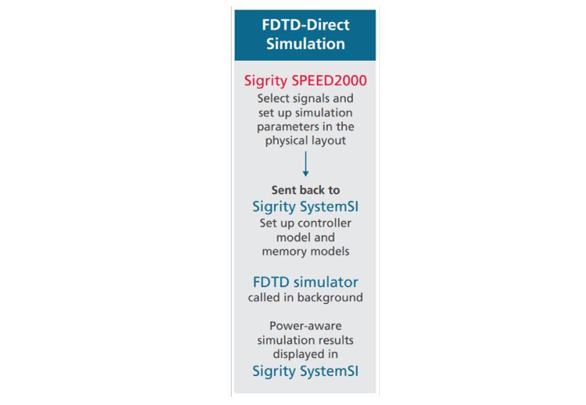
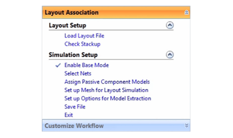
An important advantage of using the combination of Sigrity SPEED2000 and SystemSI technologies is that you do not need to generate S-parameter models for interconnect models, so you can avoid typical non-passive and non-causal problems when S-parameters are used in SPICE time-domain simulation. Those problems are typically more pronounced when a large number of DDR signals is included in the simulation, along with DDR power and ground nets and large number of decaps. Using the Layout Association (FDTD-direct) workflow, you can run what-if DDR simulations to see the impact of non-ideal power/ground on the memory interface design.
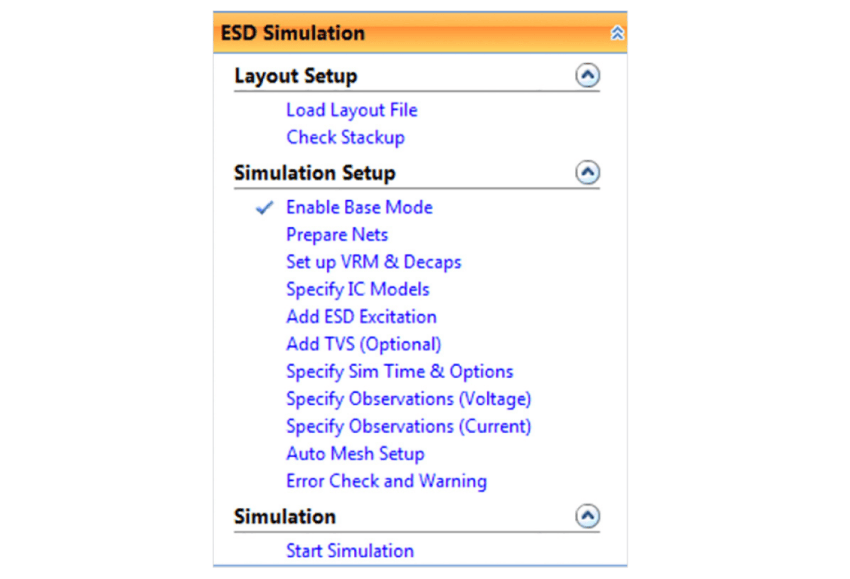
ESD Workflow
The electro-static discharge (ESD) workflow is used to test the impact of sudden and unexpected flow of electricity from an external source such as human contact or plugging in a cable with a charge. The flow includes defining the placement of an ESD gun model and then observing the impact to the board, signals, and planes. Transient-voltagesuppression (TVS) diodes and their ability to clamp the voltage peak are included in the ESD simulation.
Using the Sigrity SPEED2000 Engine as a General-Purpose SI/PI Tool
The Sigrity SPEED2000 engine offers other workflows and features that make it useful as a general-purpose SI/PI tool:
- The power ground noise simulation workflow can be used in direct time-domain power/ground noise simulation for I/O power supply. As an alternative to the Sigrity SPEED2000 tool, one could extract S-parameter models and use them in SPICE simulation. However, since I/O power supply models normally contain many early identical ports for the same power or ground nets, it can be extremely difficult to run simulation in time-domain using a SPICE simulation engine. Using the Sigrity SPEED2000 tool, you can get stable simulation results that would otherwise be very hard to obtain.
- The virtual scope—TDR/TDT workflow is a handy feature for evaluating impedance discontinuities in a PCB design. It is especially useful when you want to evaluate impedance discontinuities due to reference discontinuities and vias.
- The EMI simulation workflow enables you to run simulation using device models with correct stimulus to represent the EMI sources.
You’ll also find the following features helpful:
- Easy-to-use decap manager to assign decap models, with decap model database from Kemet, Murata, Samsung, TDK, Taiyo-Yuden, and default decap library
- Layout editing feature to make layout changes for what-if analysis
- Time-domain and frequency-domain waveform display and measurement
- Flexible 3D results visualization for signal and noise generation and propagation
- Layout virtual 3D walk-through
Fast Simulation Setups with Workflows
The Sigrity SPEED2000 tool uses workflows and wizards to guide you quickly through setup simulation. The tool offers six application-focused workflows, each corresponding to a main usage model of how it is used in SI/PI/EMI simulation.
- Trace impedance/coupling check
- SI performance metrics check
- PDN simulation
- Virtual scope: TDR/TDT
- EMI simulation
- General-purpose SI simulation
Support for a Variety of Layout Data Types
The Sigrity SPEED2000 tool performs time-domain simulation directly on physical design data. You can easily use layout data from Cadence SiP Digital Layout, Cadence Allegro Package Designer, and Cadence Allegro PCB Designer. Then, you simply attach circuit models directly to components in the layout. This way, vias, signal traces, power/gnd planes, and passive and IC component circuits are all included in simulations, providing you with comprehensive and accurate SI/PI performance results. All other major types of layout databases, such as those from Zuken and Mentor Graphics, can be translated into the Sigrity SPEED2000 tool.