Datasheet
Sigrity PowerSI 3D EM Extraction Option
Full-wave and quasi-static solver technology for IC package and PCB capable of accurate analysis of complex 3D structures
The Cadence Sigrity PowerSI 3D EM Extraction Option is three-dimensional (3D) full-wave and quasi-static electromagnetic field (EM) solver technology tailored for IC package and PCB design’s S-parameter model extraction for power-integrity (PI) and signal-integrity (SI) analysis. It provides a much faster simulation speed than other popular 3D finite element analysis tools with model reduction technology. The adaptive finite element mesh (FEM) refinement technology provides consistent accuracy for complicated 3D structures. For time-domain transient analysis, a robust low-frequency conditioning algorithm provides stable and accurate solutions down to 100Hz. The PowerSI 3DEM option’s workflow-driven user interface and automatic port generation makes the tool easy to use.
Overview
Benefits
-
 Rapidly model full IC packages or full PCBs without power and ground planes using quasi-static solver technology
 - Faster than other popular 3D FEM tools
- Output touchstone format of SZY model files
- Robust low-frequency solution
- S to RLGCZTd conversion utility to generate RLGC table
- Far-field calculation and display
- Component-based automatic port generation and grouping
- Automatic C4 bump and BGA solder ball creation
- Fiber weave wizard to consider inhomogeneous substrate
- Frequency-dependent materials support
- Surface roughness metal thickness
- Trapezoidal metal cross section
- Automated layout cutting
- Parametric sweep for design for manufacturing (DFM)
- Easily create, edit, and import 3D mechanical models
- Directly launch up from Cadence Allegro Sigrity SI/PI Base
- Distributed computing option accelerates simulation time (additional license required)
Features
Workflow-Driven Use Flow
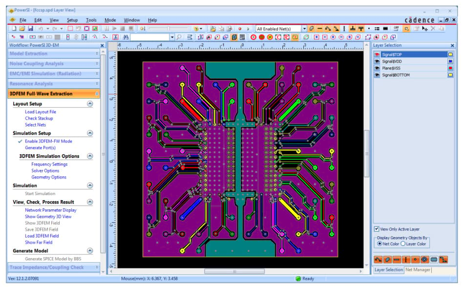
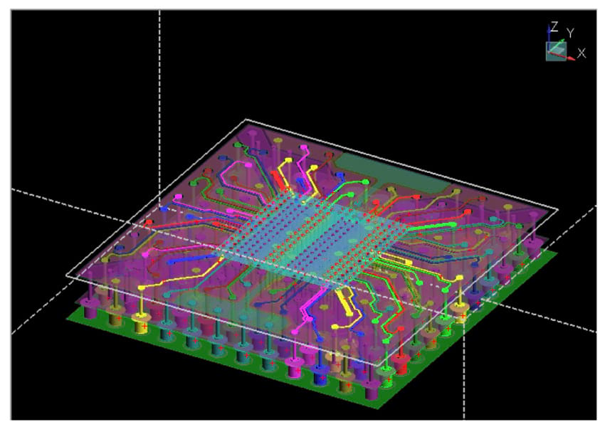
The PowerSI 3DEM option has an easy-to-use workflow that assists with set-up tasks such as stackup checking, signal and power/ground nets selection, port generation, frequency range defining, solver options, and geometry options (Figure 1 and Figure 2). A port-generation wizard is designed to automate the port generation and provide the ability to do port grouping based on user-defined areas or selected pins for power nets. Once the simulation is completed, the S-parameter curves are automatically displayed for post-processing. Other simulation results include electric and magnetic field distribution, current density, and near field.
A quasi-static extraction workflow is included to produce interconnect models that consist of resistance (R), inductance (L), capacitance (C), and conductance (G).
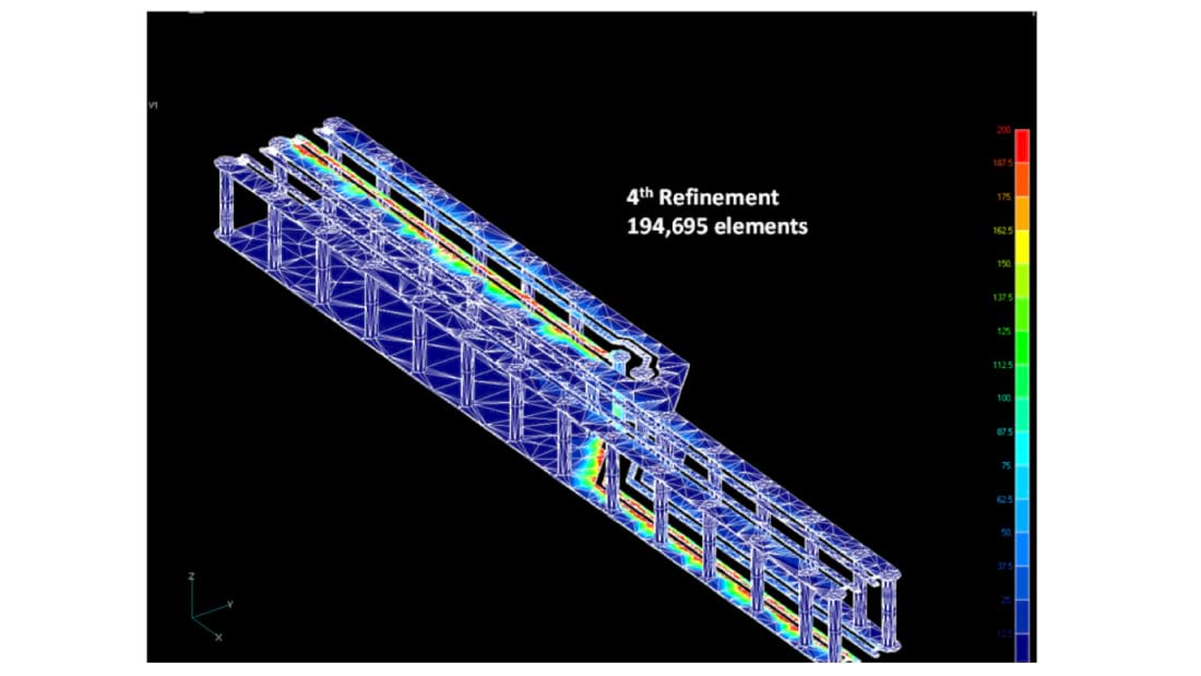
Adaptive Mesh Refinement
The PowerSI 3DEM option has adaptive meshing to ensure solution accuracy. It refines a FEM based on EM solutions from previous mesh. Only elements with higher solution errors will be refined to achieve better memory usage efficiency (Figure 3).
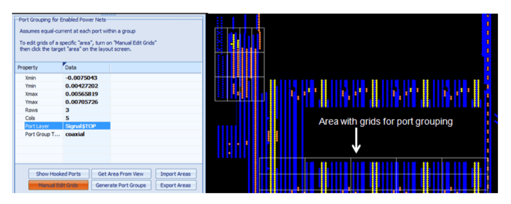
Automatic Port Generation and Grouping
The PowerSI 3DEM option provides a port-generation wizard to make port generation easy and efficient. Automatic generation based on net name and component will create lump or coaxial ports at the selected component pins.
Manual generation is also supported to select any terminals to define the port. To reduce the port number for power and SSN simulation, the port grouping can be generated by selecting an area and defining a proper partition (Figure 4).
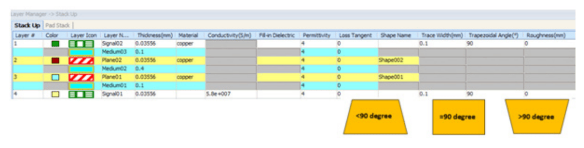
Stackup and Material Properties
The stackup and material properties in the PowerSI 3DEM option are derived from the layout database translation.
The PowerSI 3DEM option supports frequency-dependent materials based on the Djordjevic-Sarkar model to ensure causality by specifying dielectric materials for at least two frequency points. It also supports surface roughness based on root mean square (RMS) deviation of the conductor surface from a nominal smooth plane to typical RMS deviation 0.05 mils. The trapezoidal conductor cross-section can be varied from perfect rectangular shape to any angle (Figure 5).
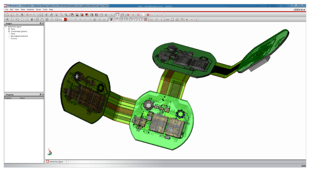
3D Workbench
The PowerSI 3DEM option option incorporates a 3D mechanical CAD GUI for creating, editing, and importing 3D solid models for 3D electromagnetic analysis. You can bring in design data from popular MCAD formats such as Acis, IGES, and STEP, as well as the Cadence Allegro and Sigrity formats (Figure 6). 3D components are easily created with parameterization and equation expressions to allow for modeling flexibility and simulation optimization. Boolean operation function is available to modify 3D components efficiently. 3D CAD geometry problems and misalignment errors can be quickly repaired with 3D Workbench’s model clean-up functions. The advanced adaptive mesh refinement algorithm allows you to automatically generate accurate meshes for small intricate 3D connectors to large complex electronic systems with enclosures.
Integration
- Available for use with Windows and Linux
- Interfaces to IC package layout databases from Cadence, Mentor Graphics, and Zuken
- Outputs S-parameter model with Model Connection Protocol (MCP) for circuit model connection