Datasheet
Celsius Thermal Solver for Electrothermal Analysis of RF/Microwave Applications
Thermal analysis inside Microwave Office software
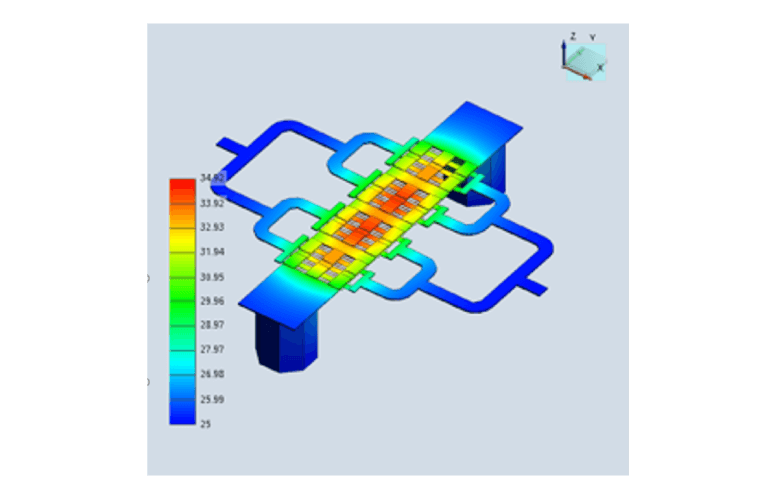
The Cadence Celsius Thermal Solver is the first thermal analysis technology designed for the electrical engineer. It delivers a complete electrothermal co-simulation technology for monolithic microwave ICs (MMICs), IC packages, RF PCBs, modules, and microwave/RF systems. The Celsius Thermal Solver is integrated within the Cadence AWR Design Environment platform, providing ready access to high-capacity electrothermal analysis for design verification and signoff of large, densely populated RF/microwave systems and high-power amplifiers (HPAs) (Figure 1).
Overview
Analyze Thermal Behavior of RF Power Devices
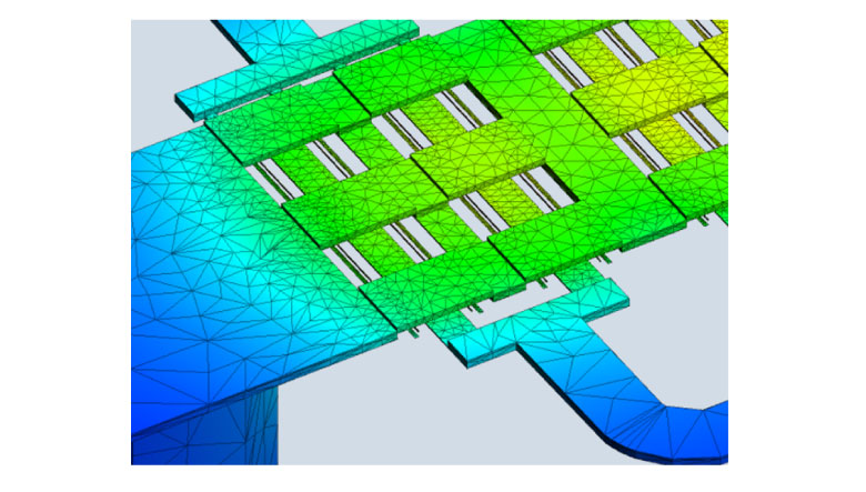
The Celsius Thermal Solver’s finite-element analysis (FEA) field solver combines with advanced adaptive meshing techniques (Figure 2) to analyze steady-state heat conduction in complex solid structures, including detailed gallium nitride / gallium arsenide (GaN/GaAs) field-effect transistor (FET) and high-electron mobility-transistor (HEMT) devices with vias and airbridges, as well as complicated packages with bumps or bonding wires.
Powerful 3D thermal distribution analysis is combined with 3D electrical simulation in an automated environment for true electrothermal co-simulation that iterates on the vital interactions between temperature and current flow.
Product Strengths
Integrated and Accessible
The Celsius Thermal Solver supports electrothermal analysis through model information sourced from Microwave Office circuit design software, including existing MMIC design data, geometries such as layout, material properties, and power-source values from RF simulation. The solver integration enables the RF designer and device modeling team to understand thermal operating conditions from within the RF design platform, eliminating bottlenecks and time delays.
Intelligent Setup
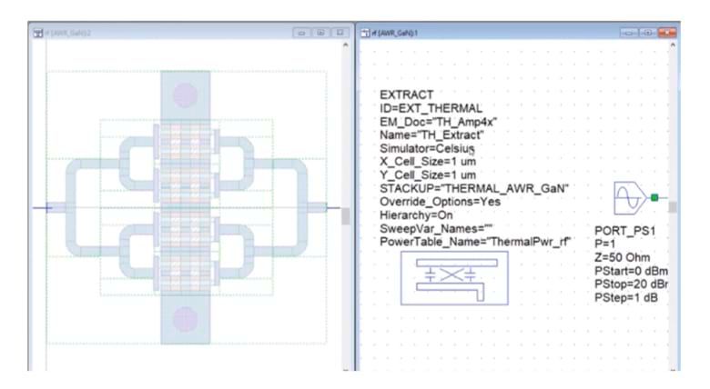
Setting up a project for thermal analysis is a straightforward process that can be performed by the individual RF designer or the library manager responsible for creating the layout process files (LPFs) that define material stackups and the device footprint cells (bare die or packaged). After adding a new thermal layer with a “Heat_” prefix to the drawing layers and EM layer mapping properties in the layout setup, the designer defines the heat source to the layout using parameterized or scripted geometries. At this point, the designer simply adds an extraction block to the schematic and selects the components to include in the thermal analysis (Figure 3).
Accurate Thermal Extraction
Designers can easily create a thermal document for analysis with the Celsius Thermal Solver directly from within the AWR Design Environment platform. The thermal document is created using the standard Microwave Office extraction block in a process that follows the same workflow that creates EM documents in AWR software. When a simulation is invoked, the information specified in the thermal document and extraction block (i.e., power dissipation data set) is passed to the Celsius Thermal Solver to set up the thermal analysis.
Thermal-Aware RF Power
In addition to producing power, RF/microwave PAs generate heat that directly impacts amplifier performance and can result in catastrophic failure. Therefore, PA designers must not only understand the electrical performance of the devices used in their design, but also their thermal profile and operating temperature. This thermal information is directly linked to the power dissipation of heat generating active devices, which can be determined using Microwave Office nonlinear harmonic balance (HB) simulation.
Microwave Office software also allows designers to easily create a data file of power dissipation for all components within a design. The extraction block then passes this power dissipation information to the Celsius Thermal Solver as part of the simulation.
Benefits
-
 Improve product reliability with fast and accurate transient simulations using realistic power dissipation information obtained from the Microwave Office nonlinear circuit simulator
 - Avoid late-stage design iterations with the mechanical engineering team by enabling electrical engineers to perform thermal simulations early in the design phase
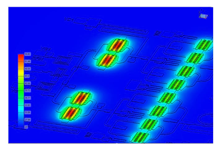
- Locate temperature hot spots with color-coded thermal heat annotation on structures to avoid the risk of failure
- Identify potential failures due to thermal stress and strain in solid materials with different coefficients of thermal expansion
- Avoid costly and time-consuming design respins with transient electrothermal co-simulations that accurately identify temperature and current density issues in 3D components such as packages, bonding wires, connectors, and transitions of connectors to the PCB
- Leverage existing project and nonlinear RF analysis to create thermal structure and analysis information, saving time and potential errors setting up simulation
Simulation Results
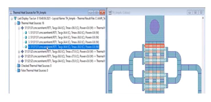
A thermal simulation can be run directly from within the AWR Design Environment platform. The operating temperature per heat source is automatically reported back to a data display in the environment (Figure 4) and linked to the corresponding geometry in the layout. This enables designers to easily investigate the temperature of a device with multiple heat sources, such as a multi-finger FET or multi-stage or balanced amplifier (Figure 5). In addition, the Celsius Thermal Solver’s native editor can be invoked in order to view additional simulation information and results, including color-coded thermal heat annotation on the structure, in order to immediately visualize the hottest region of the device.
For designers working with electrothermal models provided by the device manufacturer or MMIC foundry, the temperature data derived from the Celsius Thermal Solver analysis can be used to define the device’s operating temperature parameter under drive. Performing a new RF simulation with the updated temperature allows designers to study the impact of heat on metrics such as poweradded efficiency (PAE), gain, power compression, and bandwidth.
PDKs
The heat sources required for thermal analysis can be directly implemented into a transistor parameterized cell (Pcell). This supports foundry-authorized process design kits (PDKs) that are enabled for thermal analysis with the Celsius Thermal Solver inside the Microwave Office circuit simulation. A PDK enabled with thermal draw layers and heat sources defined within the transistor Pcell allows the RF designer to add thermal analysis to their standard design methodology without disruption or delay, resulting in significant time savings