Datasheet
Celsius PowerDC
DC and thermal analysis for packages and boards
The Cadence Celsius PowerDC environment provides fast and accurate DC analysis for IC packages and PCBs along with thermal analysis that also supports electrical and thermal co-simulation. Targeting both pre- and post-layout applications, the Celsius PowerDC approach enables you to quickly identify IR drop, current density, and thermal issues that are among the leading field failure risks. Powerful features, including sense line location optimization and simplified design-rule checker (DRC) confirmation, work in concert with the fastest available simulation to support design improvements without excess cost and schedule impacts.
Overview
Benefits
-
 Provide conclusive IR drop analysis for the complete package and board power delivery system
 - Locate current and temperature hot spots to avoid risk of failure
- Optimize voltage regulator module (VRM) sense line locations
- Address interrelated effects with electrical/thermal co-simulation
- Pinpoint crucial voltage distributions and IR drop issues at multiple component locations
- Identify hard-to-find, high-resistance routing neckdowns
- Perform analysis in order of magnitude faster than otherwise possible
- Find path and loop resistance issues for the entire power delivery network, and generate a resistive SPICE circuit model for the design
- Avoid costly implementations, engineering delays, and field failures
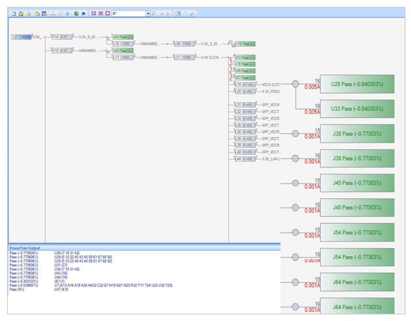
- Capture Cadence Allegro PowerTree tool data from schematic data and visualize the PDN topologies
- Using PowerTree information, simulate early and detect required component changes before the layout exists
- Automatically set up post-route analysis using PowerTree data captured during the logical design stage of PCB design
- Option to use a common analysis model library to avoid duplicate model settings for the same components
- Using the PowerTree interface, easily track changes (ECOs) to the PDN design and reuse previous setup information to quickly validate the changes
- Automatically create electrical constraints based on calculations from the IPC standard
- Interface with Cadence Voltus technology to enable chip/ package/board electrical/thermal co-simulation
Features
Electrical and thermal co-simulation
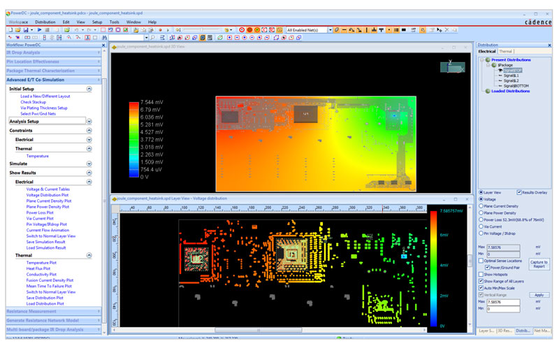
Powerful electrical simulation is combined with thermal distribution analysis in an automated environment that iterates on the vital interactions between current flow and temperature. This maximizes accuracy and fully considers effects such as the increasing electrical resistance that occurs at higher operating temperatures. This unified environment makes it easy for you to confirm that your design has met specified voltage and temperature thresholds, without having to spend significant effort sorting out difficult-to-judge impacts. The Celsius PowerDC environment incorporates a task-focused workflow tuned for DC and thermal analysis. You can bring in design data from popular PCB and IC package layout systems, and you’ll be guided through straightforward simulation set-up steps. A range of reporting and visualization options simplify issue identification, and interactive geometry editing enables what-if consideration of design improvement options.
Managing system-level IR drop
With voltage levels dropping and current requirements rising, accurate IR drop analysis is a critical step for today’s high-performance designs. Design teams that effectively manage DC loss are able to achieve required tolerances of 5% and less. They are also rewarded with welcome additional room to achieve AC noise margins. Rapid Celsius PowerDC simulations provide accurate results that take complex plane geometries and multiple voltage domains into account. Results are flexibly displayed, and post-layout DRC confirmation is provided.
Optimizing voltage regulator module (VRM) settings
Adding a VRM remote sense at the right spot helps avoid IR drop by detecting changes in current load and compensating for it. Celsius PowerDC technology provides single-step automation for the intelligent selection of the ideal VRM sense line location. This yields a margin improvement of 10% or more when compared with seemingly reasonable alternative placements. The Celsius PowerDC environment automatically balances current levels, supports grouping of multiple VRMs, and guides you as you increase VRM nominal output voltage to the maximum safe level of compensation.
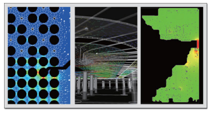
Realistic assessment of critical structures
Designs today often include fewer layers, along with higher component, via, and routing densities that combine to reduce the area for power nets. Realistically, planes are not solid but include cutouts and Swiss cheese via fields. Spreadsheet estimations and simple DC and thermal tools are only helpful if margins are ample. Complex designs with multiple sinks, various voltage levels, and irregular plane structures demand highly accurate approaches to avoid field failures such as vias that act like fuses and thermal stress in areas that neck down or have dynamic plane cuts. The Celsius PowerDC environment accurately simulates the behavior of materials from die attach to copper and important structures such as wirebonds. The electrical/ thermal co-simulation takes accuracy to an even higher level by simultaneously converging on combined current and temperature impacts.
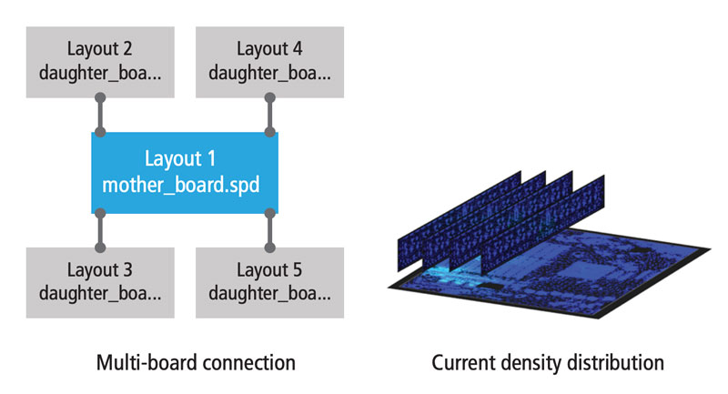
Multi-structure analysis
Multi-structure analysis provides an intuitive and easy way to perform electrical or electrical/thermal co-simulation for a multi-board system. After the analysis, all detailed results of each block are integrated into a single signoff report. This capability simplifies the setup process and reduces the analysis time, making the DC analysis of a complicated system a practical requirement for your signoff methodology.
Integration
- Works with Microsoft Windows and Linux
- Interfaces to PCB and IC package layout databases from Cadence, Mentor Graphics, Altium, Zuken, and AutoCAD