Datasheet
Cadence MaskCompose Reticle and Wafer Synthesis Suite
The Cadence MaskCompose suite is a series of software modules that work together to bring new levels of automation and efficiency to the tapeout environment. Frame generation, wafer layout, fracture preparation, generation of jobdecks and order forms, and customized paperwork is fast and consistently correct, reducing mask-making cycle times and cost while speeding time to market.
Overview
Cadence MaskCompose Suite
Within the Cadence MaskCompose suite, technology-and fab-specific requirements for the tapeout flow are captured by appropriate specialists at high levels of abstraction using a “definition module” GUI. Once captured, this flow definition information can be used over and over again by ”implementation modules” to automatically generate appropriate circuit-specific output data.
Flow definitions may be as simple or as complex as necessary to handle customer needs; however, once captured, implementation for specific designs is simple and automatic. Easy-to-use implementation modules reference definition information and quickly generate all appropriate output data.
All MaskCompose modules are designed to handle the general case and are independent of process technologies or stepper environments. This enables design and manufacturing teams to handle the equipment “mixing and matching” that is common in today’s manufacturing environments. It also serves to protect the customer’s software investment as technologies and manufacturing requirements change.
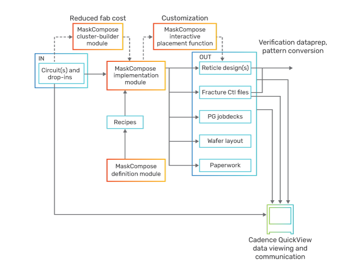
Information generated by a module at runtime is used where appropriate as input to other modules, thus, maintaining consistent correlation across GDSII data, mebes data, jobdecks, order forms, and paperwork.
The type of output data to be generated is determined by the respective definitions, and can include:
-
 GDSII and OASIS frames, which conform to the requirements of the selected fab and process technology
 - Wafer layout “shot-maps” including appropriate secondary fields
- Derived layer and fracture command files
- Mebes jobdecks
- Customized mask order forms
- Customized fab paperwork
Benefits
- Provides a highly efficient and environment-independent design tapeout system
- A definition vs. implementation paradigm allows users to take advantage of the benefits of automation (productivity, repeatability, fewer errors) while still satisfying the unique requirements of target process technologies and manufacturing environments
- Simplifies same-technology cell qualification through easy incorporation as optional test data into reticle designs
- Automatic paperwork generation boosts productivity and brings repeatability and accuracy to a process that is particularly error-prone when handled manually
- Jobdeck generation provides rapid output of PG jobdeck files that conform to the specific requirements of customer and mask maker
- Offers easy-to-use graphic user interfaces
- Automates reticle frame design synthesis and associated wafer layout
- Automates multi-die cluster building with optimizations for scribability
- Automates the building of multi-layer reticles
- Uses a drag-and-drop placement method for semi-automatic customization
- Supports fracture preparation
- Automates the generation of PG jobdecks
- Generates customized paperwork
- Accepts and outputs industry-standard formats
Features
Frame generation and wafer layout
- Support for multi-die clustering
- Support for multi-layer reticles
- Test die insertion
- Handles equipment mix and match
- Flexible scribe sizing
- Various algorithms for placing in-scribe structures
- Optional drag-and-drop mode of item placement
- Automatic generation of ID labels and barcodes
- Automatic generation of edge-seals
- Automatic die-site numbering
- Handles technology shrinks
- Optimization for best lens usage and/or wafer utilization
- Optional interactive mode for wafer layout
- Easy integration of customer programs
Frame generation within the Cadence MaskCompose environment is fast, automatic, and repeatedly correct. With requirements previously stored, the user can select a desired stepper floorplan and appropriate process technology via an implementation module. After entering a few simple pieces of information, the program is executed and generates the reticle design and associated wafer layout in conformance with the requirements set forth in the definition module.
The definition/implementation partitioning of the MaskCompose suite lends itself to a cross-discipline usage model. Floorplan definitions may be created and controlled by photomasking/ lithography or CAD specialists while actual design-specific implementations can be handled in the design group by the layout specialist.
The definition module is used to specify technology parameters, i.e., layer polarities and min/max scribe sizes. Included items may be defined as required vs. optional and assigned placement priority values. Scribe sizes may be specified in terms of a minimum size, maximum size, and an increment value by which the scribe size is increased until all required features are placed or maximum size is reached. Definitions may be constrained to allow for various types of equipment mix and match (e.g., 1X/5X mixes or stepper vendor combinations).
Multi-circuit and multi-layer mask generation
The automated cluster builder may be used to define die clusters quickly and easily. Any number of circuits of various sizes may be quickly composed into a cluster using this capability. A cluster may be full-field or may be small enough to array multiple times within the lens area of the reticle. Multi-layer reticles (MLRs) may be defined in the definition module and controlled in the implementation phase. The layers can be stripped out in the output of MaskCompose or can be stripped out in the jobdeck.
Interactive placement mode
If desired, the reticle design implementation phase may be conducted in a semi-automatic fashion in which specified items become candidates for a drag-and-drop placement methodology. This novel functionality enables easy runtime customization of floorplans by the user, and is useful in the foundry environment where requirements are fixed in a flow definition, and where optional items are made available to customers for their additions via the drag-and-drop mode.
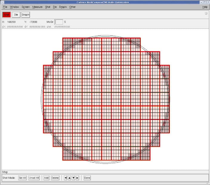
Interactive wafer module
The user also has the ability to manually manipulate and control the wafer layout or stepping patterns. The interactive wafer module provides the following user controls:
- Add or drop exposures (shots)
- Add, delete, move, copy, and place drop-in(s)
- Modify or introduce row and column shifting
- Mark additional non-yielding die
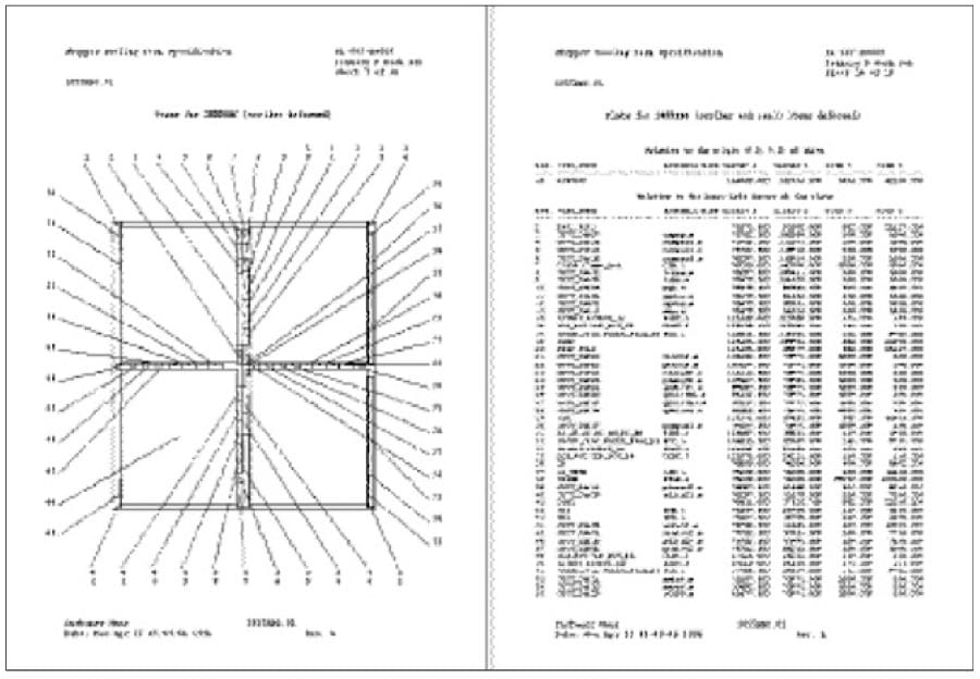
Automatic paperwork generation
- Template based
- Custom formats
- Postscript diagrams
- Access to generated and external information
- External program access
The MaskCompose paperwork generation module uses information generated by other MaskCompose modules and other provided information to rapidly create easily readable documents with customized formats. Various kinds of documents, including mask order forms, stepper tooling forms, and internal archive documentation, can be generated. Because information is extracted directly from the MaskCompose database, content consistency is assured. As an option, documents can include automatically generated postscript and pdf diagrams of generated frame data.
Information that is not captured or generated by MaskCompose can be extracted from files or prompted for at runtime by embedding appropriate commands in the various templates used. Based on the directions in a template, text entry fields, option menus, or other appropriate interface components will appear in the user’s screen at runtime to prompt for and to collect the relevant information needed to generate the desired documents.
Automatic jobdeck generation
- Rapid generation of mask vendor-specific jobdecks
- Enables mix-and-match stepper environments
The MaskCompose jobdeck generation product works cooperatively within the MaskCompose environment using existing, relevant information, made available by other modules. Frame generation definitions determine what and how many jobdecks the jobdeck generation program will output. If desired, multiple jobdecks may be defined to satisfy the varying requirements of multiple mask vendors. In mix-and-match stepper environments, multiple jobdecks will probably be required. Other relevant information made available by the frame generation and fracture preparation processes includes:
- Plate-relative chip/row values
- Slice code values
- Titling
- Magnification
- Fractured pattern names
- Address unit/spot size information