- Accurate Capture of Design Intent
- Reliable Design
- EE Cockpit and Electrically Aware Design
- System-Level Designs
- Team Design
- Design Reuse
- Design Data Management
- Library/Component Management
- Efficient Design Process
- Intuitive Design Process and Intuitive Designs
- Operating System Support
- Cadence Services and Support
Datasheet
Allegro System Capture
System architecture design and implementation for multi-board PCB systems
System architecture design and implementation are disconnected, which makes creating a system that meets cost, performance, and form factor requirements challenging. Hardware designers need tools that help them engineer their system to meet their end products’ goals within the time-to-launch window. Cadence Allegro System Capture is a scalable and easy-touse solution for fast system design intent creation that allows the high-level system architecture and functional diagram to stay connected to the detailed implementation of each board.
Overview
Accurate Capture of Design Intent
A design flow is efficient only if the schematics captured by the engineer accurately reflect the design intent. Every feature in Allegro System Capture is aimed toward this goal. The features range from helping coordinate complex data across teammates, to detecting potential problems upfront, and each feature will help ensure that the design matches the intent.
Reliable Design
Will the parts in your design withstand the voltages they will be subjected to—with margin to spare? Are there any unintended schematic errors in your design that might cause system failure?
Allegro System Capture automatically checks such situations, where manual checks can be tedious and errorprone, and thereby, generates a reliable design.
Electrical overstress
Identify components that might be approaching or exceeding the recommended overstress rating. Also, identify components that might be over-derated to help select lower-cost parts.
Allegro System Capture allows you to customize the degree of accuracy needed vs. the time needed for the analysis. Analyze derating at different temperatures, and override default SPICE models for extra precision. For outstanding use cases, elect to run only on portions of the schematic that are not already analyzed. Finally, base your review and signoff by component types used in the schematic.
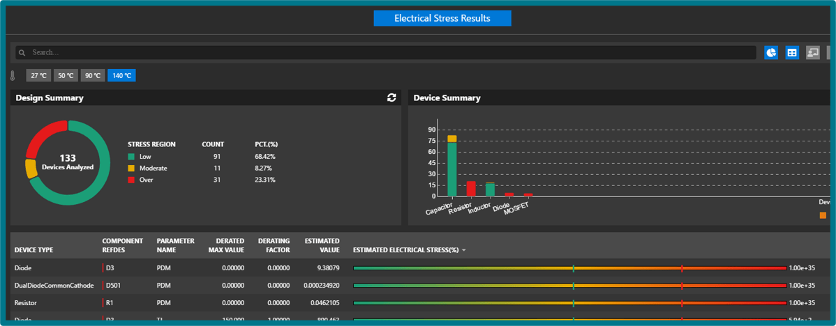
Figure 1: Electrical overstress analysis finds inadequately derated components
Schematic audit and validation
Identify and correct schematic issues with automation — issues normally caught at manual design reviews. There are dozens of schematic checks such as connectivity, device selection, protocol specific, power nets, and graphical. Detect both visual and functional issues. Configure issue priority for optimal workflow. Waive issues deemed non-issues.
Allegro System Capture comes with a set of schematic checks to prevent common errors. These checks can be customized, and new checks can be written for a company’s design review needs.
System connectivity integrity
With the system definition and detailed implementation disconnected, designers of multi-board systems must manually check connectivity across boards to ensure system connectivity integrity. This manual effort often involves writing utilities to extract data from the board files, then comparing the extracted data in a spreadsheet. Any errors in this process or lack of rigor to check it before the designs are handed off to manufacturing will result in an unnecessary spin of the board(s) to match the right signals on two sides of the mating connectors.
With Allegro System Capture, the system connectivity integrity is maintained. Any change on one board that is not matched on the corresponding board will be identified, thereby avoiding any surprises in the system integration test in the lab.
EE Cockpit and Electrically Aware Design
The schematic capture product is more than simply connecting components. It is the one point where electrical engineers should be able to seamlessly access all design data. Having all information in one place reduces the risk of translating across tools and saves time.
Integration with PSpice and Microwave Office
Analysis is a key part of the design process. Simulating in one tool, only to have to then create a schematic based on the simulation in a separate tool not only duplicates effort, but the process also creates room for errors. Allegro System Capture facilitates this flow by integrating with PSpice and AWR Microwave Office software.
RF analysis in Microwave Office software is not usually done by the same person who is responsible for either the schematic or the layout implementation on the board. This can lead to mistakes during the manual conversion process from the RF design to the PCB implementation. With Allegro System Capture, RF structures created in Microwave Office software can be imported in seamlessly. This reduces time for translation and potential errors.
With PSpice, the integration is even tighter. The simulation can be done right in Allegro System Capture with the actual schematic to be designed. In this case, no design porting or re-entry is required. Any changes made to the design due to analysis are immediately reflected in the schematic.
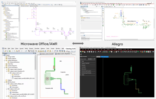
Figure 2: AWR/Allegro flow for efficient RF design enabled through Cadence Unified Library
Integrated high speed constraint-manager
Constraints are critical to creating true design intent. Allegro System Capture provides a simple, easy-to-use docked constraint manager to specify electrical constraints on a selected set of nets as they are created on the schematic canvas.
Allegro System Capture also provides full access to Allegro Constraint Manager, which is used with Allegro PCB Editor for PCB layout and routing. Having a single constraint manager prevents the misinterpretation of constraints between the front-end design creation process and the back-end PCB layout and routing process. This ability to specify electrical constraints enables a constraint-driven PCB design flow that is proven to shorten the overall design cycle and get the design right the first time. Advanced features include the ability to automatically extract, use, and override constraints from blocks added to the design.
Allegro Constraint Manager presents constraints through several separate worksheets for different types of electrical constraints. It allows the capture, management, and validation of the different rules in a hierarchical fashion. Allegro Constraint Manager allows the grouping of all the high-speed constraints for a collection of signals to form an electrical constraint set (ECSet). This ECSet is then associated with all the nets in the group. As the rules are embedded in the design, the PCB layout designer can concentrate on optimizing the physical layout for size, routability, and manufacturability, while the software automatically communicates compliance with the engineer’s performance requirements.
System-Level Designs
Complex electronic designs often span PCBs. Multiple boards need to be designed to work seamlessly together for the whole system to work as intended. System-level design features in Allegro System Capture allow system architects to design the whole system and electrical engineers to focus on individual PCBs. This allows larger systems to be designed faster and with fewer errors.
System definition and functional block diagrams
Most hardware engineers use Microsoft’s Visio or PowerPoint applications to describe the high-level architecture of their system of boards. In almost all cases, the functional diagram and detailed implementation are disconnected, which lead to a longer system-definition time. With Allegro System Capture, you can keep the high-level definition of a system synchronized with the detailed implementation of each of the boards that make up the system.
Hardware architects can hand off their system blueprint to the next phase of the design process, where a functional block diagram can be created with more information for detailed implementation. Engineers can define details of connectivity, use notes to communicate intent or requirements, and add in images to identify different sub-sections, all while creating a functional block diagram that can be linked to the detailed implementation.
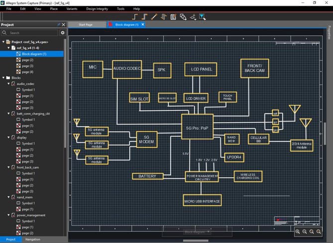
Figure 3: With system-level designs, create architectural diagrams with partitions that can be exported as subsystem projects to be independently designed
Multi-PCB system
Connect multiple PCBs as blocks while ensuring correct connectivity across the fabrics and easily generate system interconnect reports and documents for the system schematics. Ensure proper connector pinouts for mating by viewing the PCBs being connected in 3D.
Partitioning and assembly integrity
With Allegro System Capture, engineers can functionally partition a system and graphically identify the various functional blocks that make a physical board. With the partitioning integrated with the higher-level functional diagram, extended teams can provide input and feedback on the impact of the partitioning decisions earlier in the design cycle, such as whether the boards will all fit into the enclosure, if the assembly of boards will meet the cost targets, and if critical signals will have the expected performance after crossing a board boundary. If initial architectural proposals are not practical, re-partitioning can be performed, and the re-partitioned design can be returned to the design teams.
Team Design
Many designs are created collaboratively within a local team or across geographies. Allegro System Capture offers capabilities for co-designers to accurately and seamlessly communicate their design intent to their teammates.
Centralized data
Over the years, data management requirements during the design process have led to ad-hoc solutions, such as simple emails, or the development of custom systems, workflows, and solutions, leading to an increase in errors due to miscommunication, and increased time to complete the designs. Instead of storing data locally and interchanging files, stalling design processes and all-but-ensuring the probability of mistakes in the future, use Allegro System Capture’s system for centralized data.
No more questions about who owns what file, whether a file is the latest version, or if a particular party has reviewed a particular change. Centralized data enables the procurement team, electrical engineers, and layout designers all sourcing their work from the same design data and making changes to the same design data.
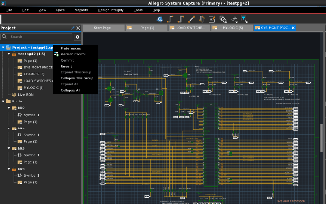
Figure 4: With a centralized data structure, all designs, libraries, and other data critical to the design are stored in one location, offering a single source of truth
LiveBOM
Current processes make updating the bill of materials (BOM) at the end of a design painful. Allegro System Capture introduces continuous updating of the BOM. Save time and reduce errors at the end of a project, and most of all, avoid redesigns caused by component unavailability.
Using our centralized data approach, electrical engineers, procurement, supply chain, and anyone else involved has visibility of the BOM without requiring interaction with the design engineer.
Team sharing
For optimal team productivity, it is common to have or at least want to have multiple team members working within the same schematic. To avoid overwriting, conflict of changes, and inaccuracies, Allegro System Capture allows read/write permission management for specific sections of the schematic. Partitioning a schematic like this enables the designs to proceed in parallel.
Additionally, if sections or pages of the schematic are in review or need individual attention, you can lock individual pages for editing to prevent teammates from overwriting each other.
PLM interface
Product lifecycle management (PLM) is evergreen in its importance for optimizing designs moving forward. Connection and integration to industry-standard PLM software should not have to be manually completed by engineers. Instead, Allegro System Capture enables a setup interface to enable quick and easy publishing.
Software products are complex, and training designers to correctly use them can require significant investment. System Capture’s intuitive PLM interface reduces the time required to get integrated with one of the most complex systems in modern corporations, and allows them to spend more time in what they’re good at — designing products.
Design Reuse
Designs are valuable IP for a company. Tried and tested designs are even more valuable because they reduce risk during bringup. Therefore, the ability re-use previous designs helps lower the total cost of design, by reducing the time to design, and reducing the risk of requiring board revisions.
Import blocks and sheets
Most new schematics reuse some portion from previous designs. Allegro System Capture provides multiple means of reusing portions of previous designs—from simple copy and paste from a design to single- or multiple-page reuses to complete block reuses. Constraints specified on the design come across to the new design, ensuring that the complete design intent is reused, not just the graphics.
Allegro System Capture further allows you to create “reuse” blocks and place them in a library for use in other designs, just as with components. The connectivity, constraints, and layout from each block can also be reused. The same block can be used multiple times in the same design without renaming or copying.
Allegro System Capture also allows users to reuse portions of existing designs created in Allegro Design Entry HDL (DE-HDL) and Allegro Design Entry CIS (DE-CIS), preserving their investment. With Allegro System Capture, logical and physical design reuse is simpler, better, and faster.
Design variants
Many designs in several market segments have design variants. With Allegro System Capture, conserve even more time and effort at the structural level. The design variants capability eliminates creating slightly different versions of the same basic design; for example, offering graduated performance levels to different market segments or addressing varying regional requirements. It enables a single base design to be derived into variants by assigning alternate sets of attributes to the components, wires, or other elements of the design. An engineering change order (ECO) applied to the base design automatically propagates to all its variants.
Allegro System Capture displays variant information on the schematics showing DNI components marked with “X”, as well as display components in a different color if a property is modified for a variant of the design e.g., (10K versus 5K). It also provides a variant table editor to enable manipulation— change value, cut and paste, etc., — of multiple entries of properties or status of components across multiple variants.
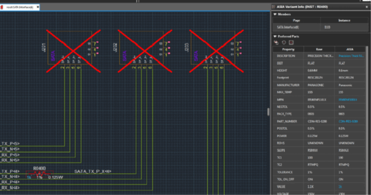
Figure 5: Variants shown on the schematics with DNI components and components
Design Data Management
Designs include many files and other moving pieces. Keeping track of files modified for different versions of the board can be labor intensive and error-prone. System Capture helps automatically maintain all the pieces involved to ensure tracking of the design.
Version control and variant management
Allegro System Capture allows not only a traditional saving of the design, but also tracks design changes made over time. Everyone in the industry has at one point had to handle multiple design files through email. Trying to keep design accuracy and the proper file tracked across multiple parties and multiple design iterations is borderline impossible.
Before fully rolling back the data of the design, view a preview of any previous design version. Fix any errors faster than ever and ensure optimal usability and productivity among teammates. Then, roll back the design to a specific version and continue designing from that point if needed.
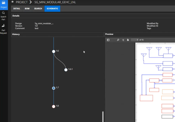
Figure 6: Version Control allows the tracking and saving of changes made, viewing of previous versions, and rolling back to a specific version
In addition, engineers can also ensure that the right connectors are chosen during the partitioning process for size and compatibility by viewing the 3D models of the connectors. This allows them to avoid surprises later in the design cycle with mismatched connectors or mismatched connector orientations.
Library/Component Management
Managing components and libraries of components for a team can be a challenge. It is important to have a centralized repository so that all stakeholders are referring to the latest and correct component information. System Capture helps in this communication between supply chain, library part creators, and the system designers without resorting to external spreadsheets and emails.
Library compatibility
Migrating tools is always a stressful event. Having compatibility with DE-HDL and OrCAD Capture- based OLB libraries makes this migration just that much smoother and less risky. System Capture helps you create new designs with existing libraries from DE-HDL as well as OrCAD Capture’s CIS libraries.
Component interface
To address the ever-changing circumstances of component availability, Allegro System Capture enables access to third-party component providers. Draw this data directly into your workflow to ensure the best component selection.
New part request
Within the new library and component information ecosystem for Allegro System Capture, use optimized workflows for part requests. Now, if a part is not available in the current library, a “New Part” request option allows you to easily request the new part with fields pre-populated with available data.
Schematic-driven placement
In many instances, placement on the layout must be driven by the symbol placement in the schematics. Allegro System Capture enables two-way cross-probing with Allegro PCB Editor to locate components in the schematics and vice versa. To help in the placement phase, place components in Allegro PCB Editor by selecting the components in the Allegro System Capture canvas. Also, place all components on a schematic page in a single step in Allegro PCB Editor.
In addition, engineers can specify component association between an active device and associated decoupling capacitors, as well as the maximum distance between the decoupling capacitors and the power/ground pins on the active component. This specification enables PCB designers to quickly place the decoupling capacitor within the required distance. With this association, Allegro PCB Editor shows a circle from the pin being decoupled to place the capacitor, accelerating the overall layout process, as discrete components in many instances make up over 66% of the components to be placed on a PCB.
Efficient Design Process
Speed of design is important to release a product as fast as possible. Allegro System Capture offers capabilities that help electrical engineers design schematics in the fewest number of mouse and keyboard clicks.
Instantiate bypass caps
Allegro System Capture also adds several efficiency improvements for frequently used processes. New features for instantiating large numbers of bypass capacitors through a form have been added for ease of use. This enables a quick creation of a clean-looking array of capacitors and helps prevent accidental no-connects or shorts that — even if we do not want to admit it — happen when dealing with larger numbers of repetitive instantiations.
Customization and extensibility
Allegro System Capture enables customization and allows users to extend the capabilities provided out of the box through a TCL (an interpreted, general-purpose, high-level programming language) interface. Engineers can write TCL programs to customize Allegro System Capture and create custom commands. The custom programs can be used for querying and modifying the design data in the system. By placing these programs in a common area, it is possible to share the efforts of all team members.
Schematics for a board
Allegro System Capture provides a modern, intuitive, easy-to-use environment to create detailed schematics for a board. With traditional schematic capture tools, engineers tend to spend a lot of time placing symbols and connecting pins. Allegro System Capture provides powerful connectivity modes that are 2X to 5X faster than traditional schematic creation tools. It also provides a way to place decoupling capacitor rails 10X faster on schematic pages near active components with only a few clicks. With online design rules checking (DRC) and packaging on the fly, Allegro System Capture allows engineers to create schematics faster and shorten the time to start the PCB layout process.
Intuitive Design Process and Intuitive Designs
Designs are complex. Small errors due to visually mistaking one net for another can have disastrous consequences. It is important for design schematics and related documentation to intuitively convey the correct electrical intent and for the CAD tool itself to be intuitive. Allegro System Capture not only offers an intuitive user interface, but it also helps create easy-to-understand and visually appealing documents.
Net Groups
Managing individual nets can be time consuming, frustrating, and error-prone. Merging nets together to created busses have been an integral solution to this issue for decades. However, what if several different busses are related to each other? Do the busses need to be managed separately? Not with Net Groups. If we consider a DDR bus with data, address, and command/control busses in a channel, they can be combined into a single DDR Net Group. A set of all the PCIe lanes could be combined into a single Net Group to keep the I/O section organized. This way, it is much easier to track signals without a crowded schematic.
Net Groups seamlessly integrate with hierarchical design blocks using Port Groups. Port Groups make it very easy and intuitive to connect design blocks with a large number of nets to other layers of the hierarchy.
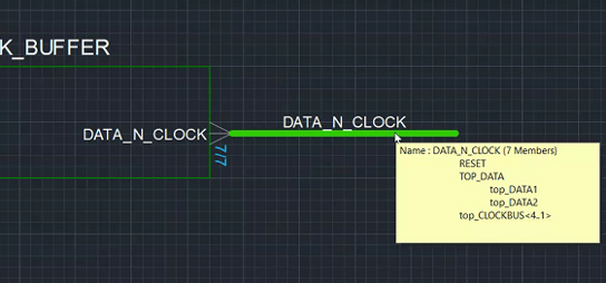
Figure 7: Net Groups and Port Groups make organizing related nets easy and facilitate both drawing and debugging of the design
Split symbols
Large symbols can be difficult to work with. Allegro System Capture splits large symbols into smaller parts to make the schematics more readable and easier to design.
Operating System Support
-
 Linux
Linux - Windows