Datasheet
Allegro PCB Librarian
Maximizing productivity in a powerful library development environment
Cadence Allegro PCB Librarian comprises an advanced library development environment for board-level design components. A comprehensive library toolset makes part creation fast and easy by reducing development time associated with large-pin-count parts from days to just minutes. Allegro PCB Librarian automates part creation tasks, eliminates manual validation, and captures revision history for schematic symbols. When used with Allegro Design Workbench, it becomes part of a scalable, comprehensive library creation, management, and component information system.
Overview
Allegro PCB Librarian
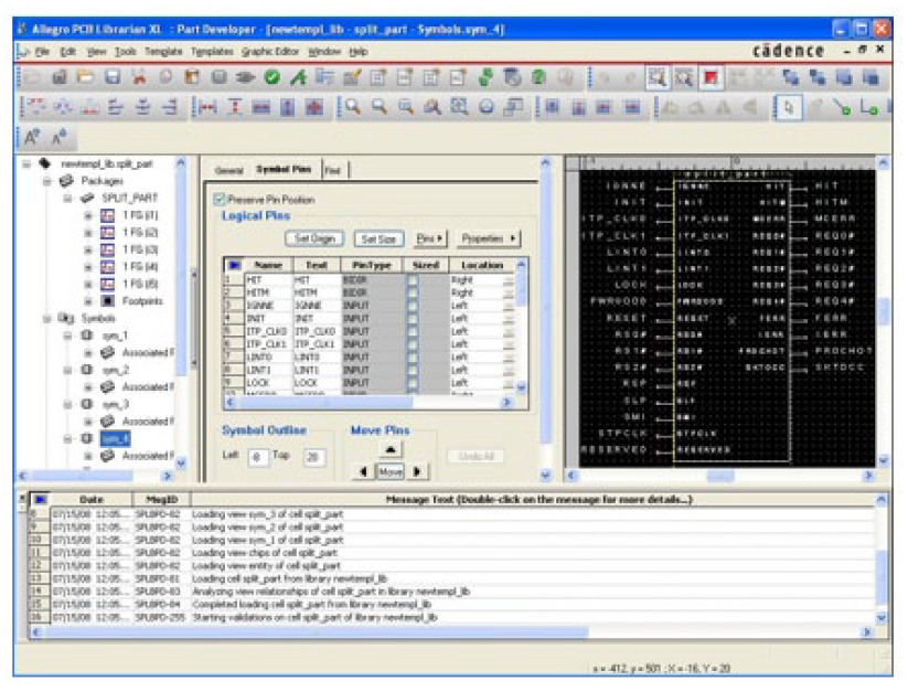
Allegro PCB Librarian maximizes the productivity of librarians who create schematic symbols, PCB footprints, and digital simulation map files for use in the Allegro PCB design flow. An easy-to-use interface, a configurable work environment, and an array of advanced verification utilities make it a powerful library development environment.
Benefits
-
 Accelerates part creation with the help of advanced part creation and verification utilities
 - Offers integrated online verification and flow verification using interactive and batch tools to provide “known-good” library data for design tools
- Enables easy import of part information from tables, grids, text files, and several other commonly used formats
- Complete for new parts
- Incremental for changed parts to expedite updates
-
- Delivers powerful graphics-editing capabilities to create schematic symbols and reusable shapes
- Provides a common library development environment for multivendor schematic design tools
- Integrates with Allegro Design Authoring and Allegro Design Workbench
Features
- Imports from more than 15 common file formats in full and incremental modes
- Exports to 5 common file formats
- Capture
- EDA XML
- CSV
- Mentor DxDesigner
- Design Architect
-
- Provides integrated spreadsheet and graphical editors for schematic symbols
- Supports the creation of reusable shape libraries
- Enables real-time, online verification
- Provides batch verification scripts
- Supports symbol property templates
- Includes configurable rule checkers for both schematic symbols and footprints
- Provides strong metadata support to enable built-in version management
Part Creation
Large–pin-count devices are becoming common for off-the-shelf components. Creating these large–pin-count parts for schematic and PCB layout can take hours or even days without special tools to accelerate part creation.
The powerful import and spreadsheet editing features of Allegro PCB Librarian aid in manipulating large–pin-count part data. Users can quickly split pins across multiple symbols, map pin names to pin numbers, and specify the visibility of power and ground pins.
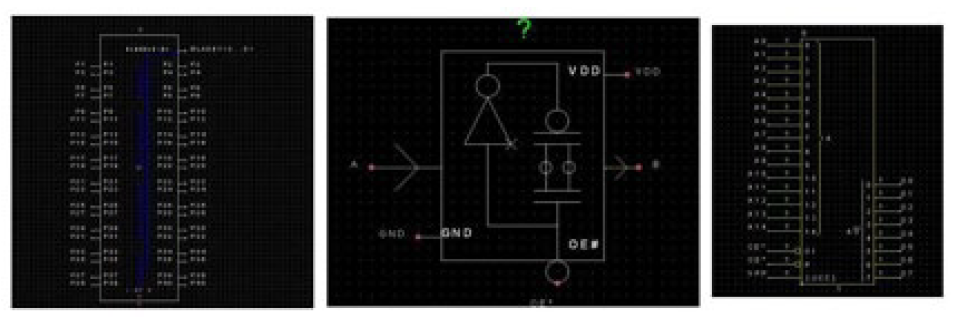
A powerful graphics editor makes symbol creation easy and quick. Users can not only create complex IEC and IEEE shapes to represent pins and functions, but also save them as reusable library elements.
The Allegro PCB footprint wizard makes it easy to create footprints by providing templates for most commonly used parts. Using the footprint wizard, users can accurately create complex footprints with thousands of pins in minutes.
Allegro PCB Librarian also provides the ability to quickly associate Hardware Description Language (HDL) models with schematic parts for both Verilog and Verilog Hardware Descripton Language (VHDL) models for use in system-level digital simulation.
In Allegro PCB Librarian, all changes made to a part are tracked and the differences between part versions are captured and saved automatically. This removes the burden on librarians to record all changes made to a part. Check-sum verification is integrated into the system and tracks any modification to parts made outside the library system. This protects the data against unauthorized modifications and notifies librarians when a modified part is opened in the system.
Multi-Vendor Support
Allegro PCB Librarian allows users to create symbols for Allegro Design Entry HDL, Cadence OrCAD Capture, Mentor Graphics Viewdraw/DxDesigner, and Mentor Graphics Design Architect. Part information can also be exported in comma-separated values (CSV) and XML formats. This allows single sourcing of part data in companies where librarians need to support designs teams who use multiple schematic editors with Allegro PCB Designer. Direct export to multiple schematic editor formats makes it easy to develop parts in a single toolset for use with multiple schematic editors.
Export in XML can be used to publish part data for external access or verification. Exporting text files allows users to store “electronic datasheets.” The ability to convert from CSV to PDF helps in the migration of parts from other vendors.
Allegro PCB Librarian also allows users to save parts in formats compatible with older releases of Allegro PCB Designer and Allegro Design Entry HDL. This enables users to adopt the latest librarian releases and features while still supporting previous releases of Allegro solutions.
Data Import
Allegro PCB Librarian provides a variety of import options and utilities to accelerate part creation. Users can create schematic parts by importing part data in formats such as:
- EDA XML
- Si2 PinPak XML
- VHDL
- Verilog
- Synopsys PTM models
- CSV and text files
- Die text
- Pin grids
- Pin tables
- Cadence OrCAD Capture
- Mentor Graphics DxDesigner
- Mentor Graphics Design Architect
- Allegro Package Designer
- FPGA (Xilinx, Actel, Altera)
- IBIS
- DML
Die file import enables co-design while FPGA import helps in implementing FPGA flows in front-end design. With IBIS and DML model import, front-end models can be easily created from third-party highspeed models.
User-configurable data translation rules make it easy to customize data import. These rules manipulate part, pin, and property names as well as other part details.
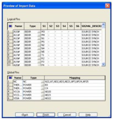
Allegro PCB Librarian checks the data being imported for consistency and validity, flagging errors upfront. A preview window allows users to review the part data before the part is created. These reduce the chance of errors in the source data being propagated into the part.
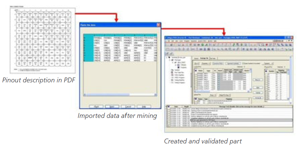
Datasheet Mining
The ability to read pin tables and pin grids makes it easy to create parts from descriptions in PDF datasheets. Users can copy pin-out/ball-map diagrams from datasheets into Allegro PCB Librarian. The data is automatically interpreted and can be fine-tuned to meet company naming standards.
Additionally, users can copy complete tables of information from datasheets with configurable translation of pin types and bus notations.
Schematic Symbol Editing
Allegro PCB Librarian comes with a powerful graphics editor for creating reusable shapes and schematic symbols. An editable spreadsheet with symbol information and a symbol editing canvas with expert features, such as separate grid controls for pins and non-pin objects, give users the flexibility to do bulk operations and intricate graphics work according to their needs.
Automatic symbol generation based on user preferences makes it easy to create large-pin-count devices—devices that might have thousands of pins distributed among dozens of symbols. A simple pin distribution interface makes it easy to move pins between symbols to meet engineering requirements. The spreadsheet editor for part information speeds many part development operations, including:
- Converting scalar pins to vector pins and vice-versa
- Expanding and collapsing vector pins
- Switching between visible and invisible power pins
- Filtering and hiding operations
- Finding and replacing
A comparison UI makes it easy to compare interfaces of various part entities including footprints, schematic symbols, and SI models.
The ECO import mode makes implementing incremental changes remarkably easy. This mode retains original data, while allowing new, possibly conflicting data to be imported. The data can then be compared and resolved to produce parts. The ECO mode greatly reduces rework in cases where input data changes frequently. The ECO preview window allows users to view and evaluate newly imported data before committing to the change.
PCB Footprint Editing
The PCB footprint creation process is designed to simplify the ever-increasing complexity of today’s package models. A powerful wizard enables users to quickly create footprints using templates that handle most package types—including DIP, SOIC, PLCC/QFP, PGA/BGA throughhole discrete, SMD discrete, SIP, and ZIP. The pad designer facilitates the creation of any shape pad and padstack. It allows users to define the pads for each layer in the stack-up as well as various mask layers, hole types, and slots.
Validation
Allegro PCB Librarian provides extensive part validation capabilities with built-in checks at every stage of the part creation process. For imported data, validation occurs at the time of import. When data is entered in the part editor, it is checked in real time for valid characters, lengths, permitted values, and syntax. Symbolpackage checks guarantee that parts will work in the complete PCB design flow. Footprint validation routines allow users to compare pin numbers specified at the time of schematic symbol development with PCB footprints. This online check ensures that schematic components and footprints are in sync.
Most verification is done in real time without leaving the editor. Additionally, batch validation provides automated design flow verification that significantly reduces the burden on librarians. Users can run detailed packaging checks that instantiate the schematic symbol in a schematic sheet, create a netlist, and place the footprint into a layout file or quick checks that help them determine, in considerably less time, if a part can be packaged.
User-defined symbol and footprint checks can be built for schematic parts and footprints. These can operate on one part at a time or on complete libraries.
Comprehensive rule development and checking guidelines are provided both for schematic symbols and PCB footprints.
Consistency checks are done whenever a part is saved or loaded for editing. Part error status is stored with the part and displayed whenever the part is opened or closed. Allegro PCB Librarian provides a standard rule set and a developer’s toolkit for building user-defined rules. Using these rule sets and the built-in part validation system, librarians can push parts through the advanced rule checking and advisement system. This reduces costly design iterations by ensuring that a part is correct from the start.
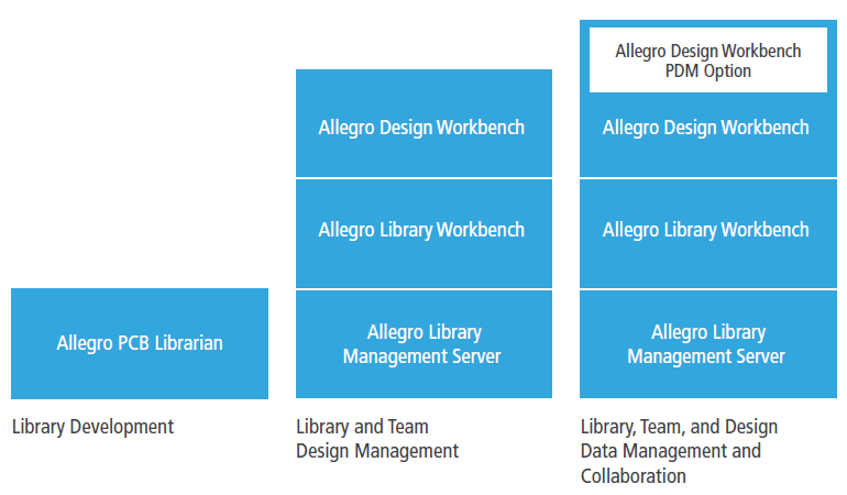
Allegro Design Workbench Integration
Allegro PCB Librarian is an integral part of Allegro Design Workbench. When combined, these technologies comprise the most powerful board-level library and design data management system available today. It allows users to manage and distribute their Allegro schematic and PCB libraries. Component information can be included from datasheets, ERP, MRP, or other sources.
By setting up a standardized part development flow across their organization, users can reduce errors and accelerate library development. This approach significantly increases productivity and improves the quality of their library. Configurable flow management capabilities allow users to manage their library development process and tailor it to their specific needs.
Operating System Support
- Sun Solaris
- Linux
- IBM AIX
- Windows
For More Information
Contact Cadence sales at 1.800.746.6223 or visit www.cadence.com for additional information. To locate a Cadence sales office or channel partner in your area, visit Contact Us.