Brochure
Initiator Controller IP for MIPI I3C
Overview
Overview
Rapidly increasing numbers of sensors creates new design challenges for mobile, automotive, and internet of things (IoT) devices. These design challenges include significantly higher signal count and increased bandwidth requirements. To address these challenges the MIPI Alliance has defined the I3C interface for connecting all the sensors in a system.
The Cadence IP Family for MIPI Protocols delivers area-optimized interface IP with the low power and high performance required for today's leading-edge devices. One member of this family is the Cadence Initiator Controller IP for MIPI I3C.
Compliant with the latest MIPI I3C specification and legacy compatible with I2C, the Controller IP is engineered to quickly and easily integrate into any mobile embedded system-on-chip (SoC) device and expand sensor communication capabilities with better power efficiency.
Developed by experienced teams with industry-leading domain expertise, verified by silicon-proven and mature I2C IP and validated on a FPGA platform to reduce risk for designers, the IP will connect seamlessly to the Controller IP.
The Controller IP is part of the comprehensive Cadence Design IP portfolio comprised of interface, memory, analog, system, and peripheral IP.
Benefits
-
 Superior performance to power ratio compared to established sensor interfaces - I2C, SPI
 - Complete solution—complementary initiator/ responder IP
- Fully verified on FPGA
Key Features
- Support for multiple transmission modes: Single Data Rate (SDR) and High Data Rate (HDR)
- Support for in-band interrupts, hot-join, peer-to-peer request, current initiator control request
- Compliant with the latest I3C specification
- I2C legacy device support
- Support for I3C common command codes
- Arm AMBA APB interface support for register access
- Support for Full, Reduced, and Simplified data ports
- Command queue support
- Dynamic address assignment (DAA) support
Product Details
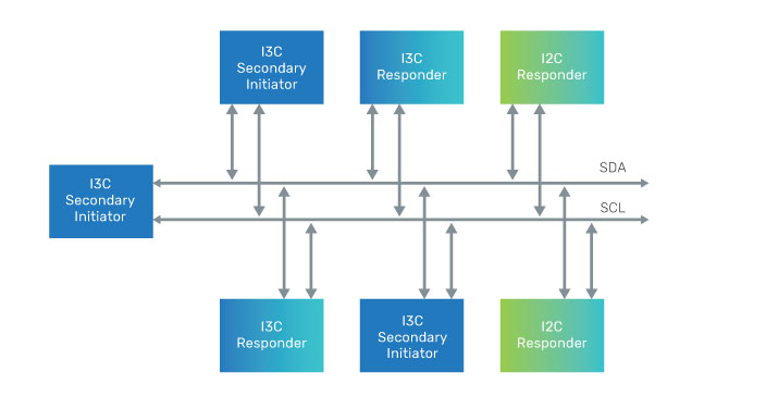
The Controller IP is compliant with the MIPI Alliance I3C sensor specification for embedded systems applications enabling the incorporation of more sensors in a device.
This is a soft IP ideally suited for implementation in ASIC SoC designs with increasing numbers and types of sensors. It provides reduced energy consumption and higher performance over legacy designs.
Architecture
The Controller IP is split into hardware and software functions. The I3C manager handles packet forming and message handling in hardware. It includes an interconnect protocol and support for a 32-bit APB responder mode to access the registers interface and external DMA. There is an optional FIFO to reduce load on the host servicing the I3C interface. It functions primarily as a initiator controller, with optional secondary initiator support.
The IP supports I3C standard-compliant protocols including legacy I2C mode, backward compatible to Fast Mode (FM— up to 400kHz) and Fast Mode Plus (FM+—up to 1MHz), single data rate I3C mode (up to 12.5MHz), and optional High Data Rate (HDR-DDR).
The IP features include I3C common command codes, DAA, in-band interrupts, hot-join request, and current initiator control takeover request support.
Clock Domains
The default system configuration will define fully asynchronous clock structure, no correlation between pclk and sys_clk. Pclk and sys_clk are asynchronous to each other (in phase and frequency). Proper synchronization between pclk and sys_clk allows any combination of frequencies between 50 and 200MHz.
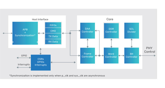
Host Command Interface
The host command interface provides a command interface that can be queued. Commands are sent through the APB interface, with optional payload (write data or read data). Two separate RX/TX data FIFOs enable the controller to have mixed write/read command in the command queue FIFO. Immediate command provides a mechanism to send higher priority commands (CCC commands only).
Configurations Options
- FIFO (RX and TX FIFO depth)
- Secondary initiator support
- HDR-DDR mode enable/disable
- Command queue depth
- I3C devices that can reside on the I3C Bus with maximum number
Related Products
- Simulation VIP for MIPI I3C
- Responder Controller IP for MIPI I3C
- Controller IP for MIPI I2C
Deliverables
- Documentation—Integration guide, user guide, and release notes
- Clean, readable, synthesize-able Verilog RTL
- Synthesis scripts
- Sample verification testbench with integrated BFM, monitors, and sanity tests
For more information, visit Design IP.