Brochure
Device Controller IP for USB 3.1
Overview
Overview
As the Universal Serial Bus (USB) standard continues to be the common connectivity solution for both established and new, emerging types of consumer devices, the need for a robust and industry proven USB IP from a trusted provider is spreading to new markets and applications.
Certified for compliance with the USB 3.1 specification, Revision 1.0, the Cadence Device Controller IP for USB 3.1 leverages deployment in numerous applications and offers to customers reliable and competitive product for all peripheral devices that make use of a USB connection.
The target applications for the Cadence USB Device Controller IP include thumb drives, SSDs, HD video cameras, and other PC peripherals. Thanks to configurable system interface and endpoint space, the controller can be customized to fit single or multiple applications within an SoC.
The Device Controller IP can be delivered with either a low-level or GPL Linux driver to ease integration into the target appli-cation. When integrated with the Cadence PHY IP for USB 3.1 Type-C, the Device Controller IP provides a complete solution for the next generation of USB applications.
Benefits
-
 Superior performance to power ratio compared to established sensor interfaces - I2C, SPI
 - Complete solution—complementary initiator/ responder IP
- Fully verified on FPGA
Key Features
- Support for multiple transmission modes: Single Data Rate (SDR) and High Data Rate (HDR)
- Compliant with the latest I3C specification
- Support for I3C common command codes
- Support for Full, Reduced, and Simplified data ports
- Dynamic address assignment (DAA) support
- Support for in-band interrupts, hot-join, peer-to-peer request, current initiator control request
- I2C legacy device support
- Arm AMBA APB interface support for register access
- Command queue support
Product Details
The following sections describe the major blocks and functions of the Device Controller IP.
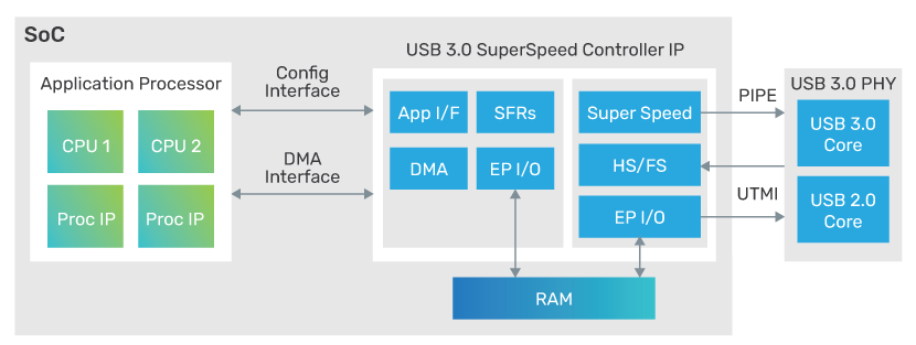
SuperSpeedPlus Controller
The SuperSpeedPlus controller implements the USB 3.1 protocol for peripheral devices. Functions are distributed among link layer and protocol layer modules, which allows the Device Controller IP to reach maximum transfer speeds close to the theoretical maximum value.
AXI Initiator Interface
The AXI Initiator Interface is designed to integrate to an application specific memory controller for providing operational data to the Cadence USB 3.1 controller. This interface is used to gain access to application memory. DMA is used to access data structures and related information during normal operation.
APB4 Responder Interface
The APB Controller interface allows for S/W programmability of the Cadence USB 3.1 controller. It provides control and operation status information to the driver software.
System Power Management Interface
When the application desires to employ Power Management, these signals provide an interface to the System Clock Controller to enable dynamic power saving states.
Interrupt Interface
This interface provides interrupt signals to the external CPU for various events detected within the Cadence USB 3.1, including Peripheral-defined interrupts.
MSI Interface is included in the Cadence USB 3.1 to support application interrupts. If enabled, the core will generate 32-bit write operation at AXI Initiator Interface instead of using interrupt lines. The address and value of the write is controlled by xHCI Extended Message Interrupt Capability.
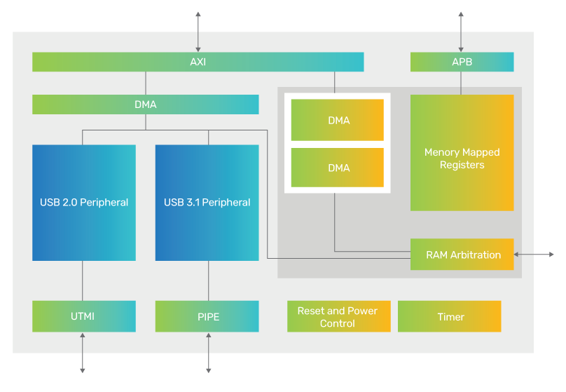
On-Chip Memory Interface
SPRAM memory modules are used to store information about Slot/EP state and as a scratchpad memory for the Cadence USB 3.1. DPRAM memory is used for USB transfers buffering and clock domains synchronization.
Availability
The Device Controller IP is available with the configurations below and supports the following protocols:
| Protocol | Speed |
|---|---|
| USB 3.1 | 10Gbps/5Gbps |
| USB 2.0 | 480Mbps |
Related Products
- Verification IP for USB Protocols
- PHY IP for USB 3.1
- PHY IP for USB 3.1 Type-C Related Products
Deliverables
- Synthesizable RTL
- Testbench
- Synthesis and simulation support files
- Documentation
For more information, visit Design IP