Brochure
Design IP for MIPI D-PHY for TSMC
Overview
Overview
Today’s leading-edge mobile devices contain increasingly integrated functionality that supports growing volumes of content and video, more ways to control and interact, and longer battery life. The MIPI Alliance defines semiconductor standards that support growing complexity and reduce device form factor. The Cadence family of interface IP for MIPI protocols is leading the way with mobile-optimized low power and high performance. Compliant with the specification for MIPI D-PHYSM with speeds up to 2.5 Gbps per lane, the Cadence Design IP for MIPI D-PHY supports CSI-2SM and DSI protocols.
Developed by experienced teams with industry-leading domain expertise and extensively validated by multiple hardware platforms, the PHY IP is silicon-proven and shipping in high volume in multiple mobile devices. The PHY IP is engineered to quickly and easily integrate into any design, and to connect seamlessly to a Cadence or third-party PPI compliant controller. Implemented on several popular semiconductor processes, the PHY IP provides a cost-effective, low-power solution for demanding mobile applications.
The IP is a mixed-signal PHY consisting of a D-PHY transmitter and a D-PHY receiver. The PHY IP is developed and validated to reduce risk for designers so that their system on chip (SoC) can be first-time right. Developed and available early in the life-cycle of the most advanced semiconductor process nodes, the PHY IP is designed to be robust under varying signal strength and noise conditions.
The PHY IP is part of the comprehensive Cadence Design IP portfolio comprised of interface, memory, analog, and systems and peripherals IP
Benefits
-
 Improved low-power control with LP mode and ULPS support
 - Wider timing margins with matched analog design
- Greater functional testing with datapath loopback
Key Features
- Compliant to MIPI D-PHY v1.2
- Scalable up to four lanes in each direction
- Supports ULPS and contention detection
- Integrated BIST capable of producing and checking PRBS
- 8-bit PPI interface
- Matched analog design for low inter-lane skew
- Compact footprint and low-power dissipation
- Automatic termination control in high-speed and low-power modes
Product Details
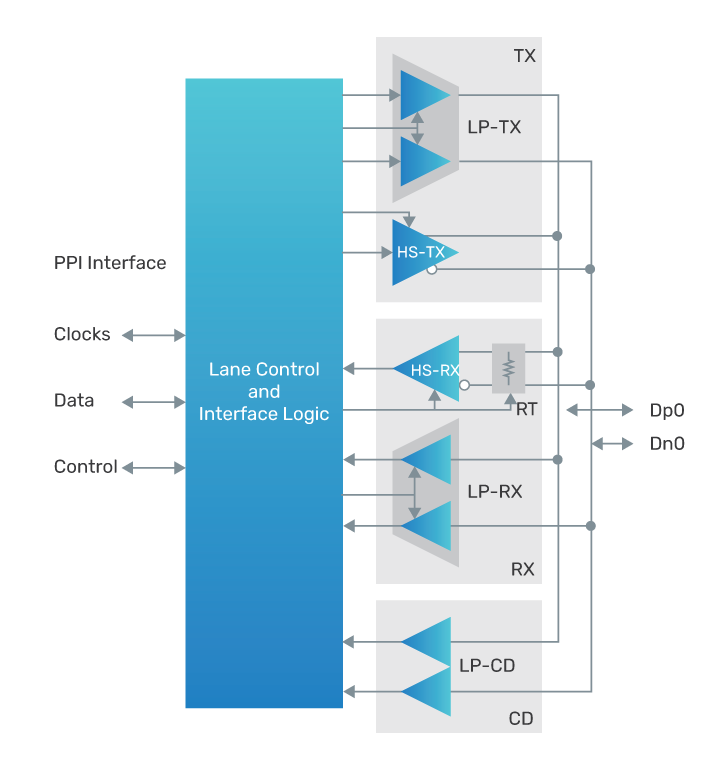
The PHY IP is a mixed-signal design that uses optimized and matched analog design for reducing clock-to-data lane skew and maximizing timing margins. It consists of MIPI D-PHY transmitters (HS-TX and LP-TX), receivers (HS-RX and LP-RX), low-power contention detector (LP-CD), and lane control and interface logic (CIL). The CIL can be configured for either data or clock lanes.
D-PHY Architecture
The PHY IP provides complete flexibility with process, library, floor plan, I/O pitch, packaging, metal stack up, routing, and other physical parameters, giving the interface designer complete control over the physical layer.
The IP is implemented with a modular architecture, which allows a single clock lane to work with up to four data lanes in each direction.
Control and Interface Logic
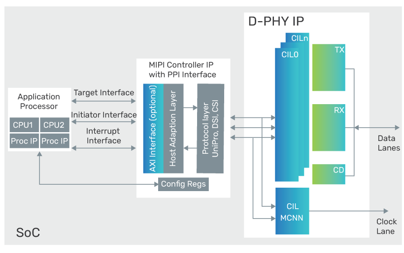
The CIL implements the PHY-level protocol interface (PPI) found in Annex A of the MIPI Alliance Specification for D-PHY. PPI supports MIPI CSI-2 and DSI specifications. The CIL can be configured for any of the lane types defined in the D-PHY specification, including bidirectional and unidirectional lanes.
Transmitter and Receiver
The PHY IP is implemented as separate transmitter and receiver blocks that support high-speed (HS) and low-speed (LS) signaling
Transfer speeds up to 2.5Gbps per lane in HS mode and up to 10Mbps in LS mode are supported. The receiver block also supports low-power contention detection (LP-CD).
Availability
The PHY IP is available with various configurations and supports the following protocols:
| Protocol | Speed | Process Node |
|---|---|---|
| D-PHY v1.2 | 2.5 | TSMC 12FF |
| D-PHY v1.2 | 2.5 | TSMC 16FF |
Related Products
- Design IP for MIPI M-PHY
- Receiver Controller IP for MIPI CSI-2
- Transmitter Controller IP for MIPI CSI-2
- Transmitter Controller IP for MIPI DSI
Deliverables
- GDS II macros with abstract in LEF
- Verilog post-layout netlist
- STA scripts for use at chip or standalone PHY levels
- Liberty timing model
- SDF for back-annotated timing verification
- Verilog models of I/O pads, and RTL for all PHY modules
- Verilog testbench with memory model, configuration files, and sample tests
- Documentation—integration and user guide, release notes
- Verification IP set up files
For more information, visit Design IP