Application Note
Improving the Second-Harmonic Passband Rejection of Microstrip Side-Coupled Filters
Filters are used in communication systems to reject unwanted signals from propagating through a network. These signals may be interferers from other systems or they may be generated by the nonlinear behavior of components within the network. For instance, an amplifier driven into nonlinear operation will produce spectral components at harmonic frequencies.
Filters provide sufficient rejection at harmonic frequencies. Because of their low cost and easy manufacturability, side-coupled filters constructed from PCB-based microstrips are widely used throughout the industry. One of the main problems of the side-coupled filter is its limited rejection of the second harmonic. This application note demonstrates a solution that mitigates this problem through the introduction of notch-filter elements that improve the overall rejection of side-coupled filters at the second harmonic without significantly affecting the filter-passband behavior.
Overview
Classic Side-Coupled Filter
In this application, a side-coupled filter (also known as a parallel-edge coupled filter)1 is built from several sections of coupled transmission lines in which each section is offset from the previous section, resulting in a relatively wide footprint. The initial filter design was created using the filter synthesis tool in Cadence AWR Microwave Office software, based upon user-defined filter characteristics such as passband frequencies, passband ripple, rejection at the stopband, and more. The resulting circuit (Figure 1) defines the microstrip layout for manufacturing and/or electromagnetic (EM) analysis purposes.
Side-Coupled Filter Using In-Line Coupled Line Pairs
To reduce susceptibility to EM interference, the filter can be housed in a waveguide. However, there is a risk of higher-order waveguide-mode propagation, unless the guide is narrow enough. So even if the filter itself blocks the second harmonic of the signal in microstrip mode, this application attempts to make the filter as narrow as possible in order to guarantee that the waveguide does not support the second-harmonic propagation in the waveguide modes.
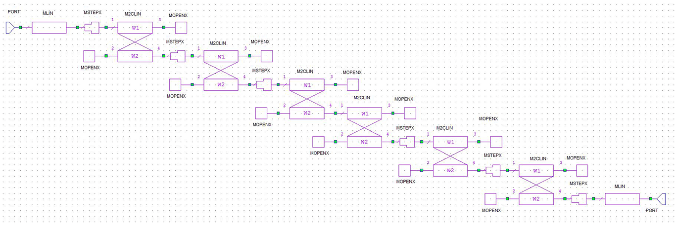
In this design example, transmission lines will be added between the pairs of coupled lines, which will allow the pairs to be rearranged so they are in line. This change to the layout will result in a narrower footprint, enabling a waveguide with higher cutoff frequency to be used to house the filter. Figure 2 shows a schematic of a tapped-microstrip side-coupled filter2 with the added microstrip lines and all pairs in line.
Adding Notch Elements
A stop-band notch filter is created with the addition of an open-circuit microstrip stub a quarter wavelength long at the center frequency of the second-passband harmonic. At the frequency of the second-passband harmonic, the stub’s open circuit impedance will be transformed to a short-circuit impedance on the transmission line that connects the coupled pairs and thus provides the rejection at the second harmonic, canceling the second passband. The capacitive loading associated with the open stub at the first-passband frequency will only slightly impact the first-passband performance.
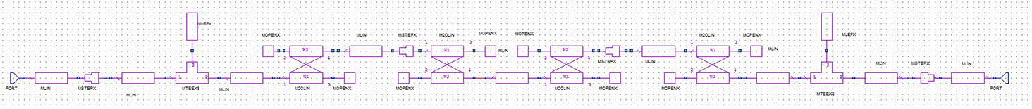
The introduction of interconnecting transmission lines between the coupled-line pairs allows the insertion of a second harmonic quarter-wavelength open stub at the center of the half-wavelength coupled-line resonator, as shown in Figure 3.

Obviously the stubs tend to make the filter wider again. The layout can be made more compact by using radial stubs and/or bending the stubs. A circuit-model optimization followed by a verification EM simulation suggests the layout shown in Figure 4.

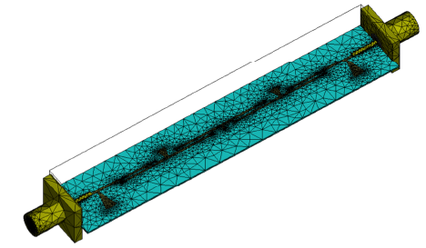
The filter dimensions are such that it can be housed in, for instance, a WR-22 waveguide with cutoff frequency of 26.3GHz. The waveguide changes the filter response somewhat, so a fine-tune redesign is necessary. Moreover, a coax-connector model in full 3D simulation can be included using the Cadence AWR Analyst finite-element method (FEM) EM simulator within the Cadence AWR Design Environment platform. The coax-to-microstrip transition can be modeled as a separate problem, and, if necessary, a matching section can be designed.
Figure 5 shows the filter response of Figure 4 with and without the waveguide, still without connectors. It can be observed that there is a slight upward shift of the passband frequency, but the second-harmonic rejection is as good or better than before.
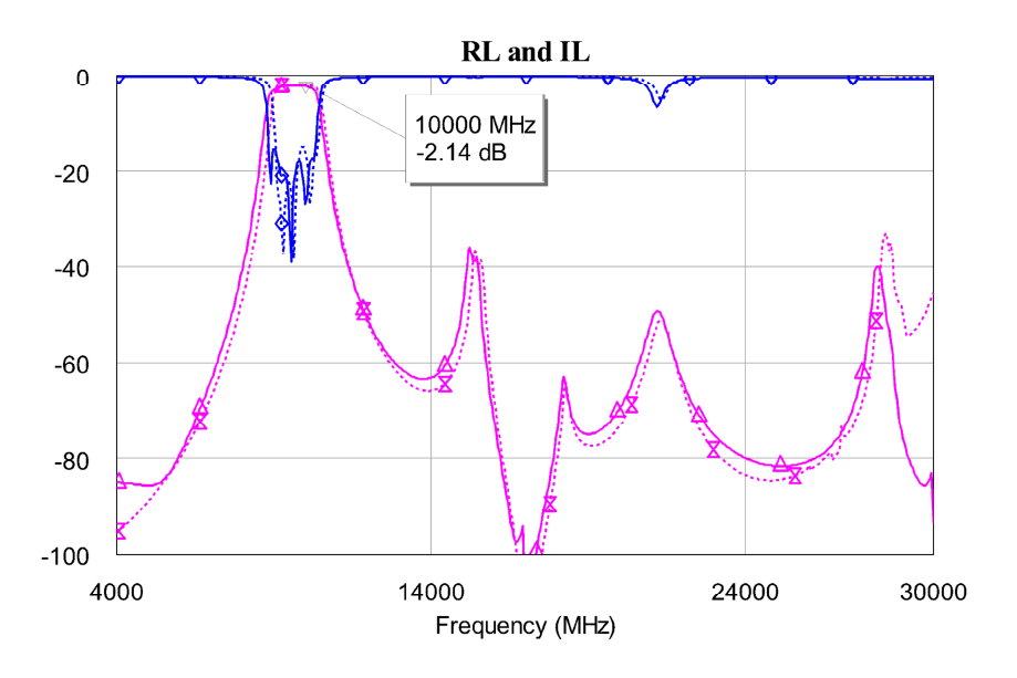
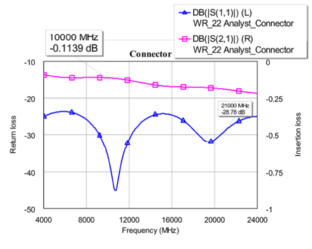
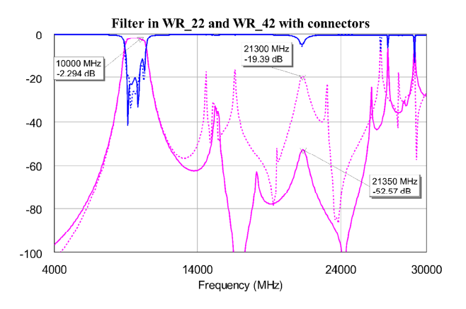
Looking at the connector transition alone (Figure 6), there is no significant mismatch up to the second harmonic, while an additional insertion loss of 2 x 0.11dB = 0.22dB at passband is expected. Composing the complete simulation model in AWR software results in the geometry and mesh shown in Figure 7 and the response shown in Figure 8. The insertion loss has increased 0.15dB and the second harmonic rejection stays well below -50dB. For comparison, the same filter was simulated in a WR-42 waveguide with 14.1GHz cutoff frequency and the results are also shown in Figure 8. The second harmonic rejection is 30dB worse, due to the waveguide effect that now can propagate down the guide.
Conclusion
The use of an inline topology for a side-coupled microstrip filter results in a narrower footprint with minimal impact on filter performance. This topology enables improvement of the rejection of higher harmonics due to reduction in the filter width and, consequently, in the waveguide effect, when the filter is mounted on a waveguide cavity. This application has demonstrated that the implementation of notch filters for second harmonic rejection using open stubs is practical and a rejection of 50-60dB can be achieved with minimal degradation in the passband performance.
References
- G. Matthaei, L.Young, E.M.T. Jones, Microwave filters, Impedance – Matching Networks and Coupling Structures, Artech House, Norwwood, MA, 1980.
- J.S. Wong, “Microstrip Tapped-Line Filter Design”, IEEE Trans. MTT-27, 1, 1979, 44-50