MIPI D-PHY, C-PHY, and A-PHY Verification IP for your IP, SoC, and system-level design testing
Cadence provides a mature and comprehensive Verification IP (VIP) for the D-PHY/C-PHY/A-PHY, which is part of
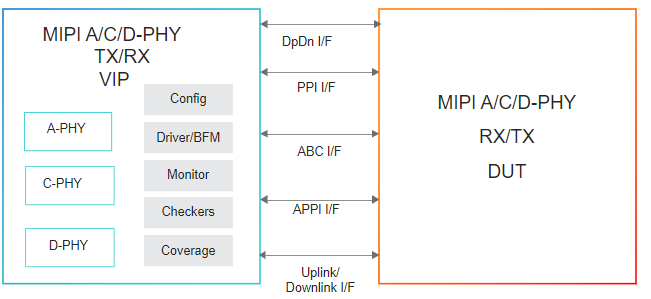
the MIPI family. Incorporating the latest protocol updates, the Cadence Verification IP for
D-PHY/C-PHY/A-PHY provides a complete bus functional model (BFM), integrated automatic protocol checks, and
coverage model. Designed for easy integration in testbenches at IP, system-on-chip (SoC), and system
levels, the VIP for D-PHY/C-PHY/A-PHY helps you reduce time to test, accelerate verification closure, and
ensure end-product quality. The VIP runs on all major simulators and supports SystemVerilog verification
language along with associated methodologies, including the Universal Verification Methodology (UVM) and Open
Verification Methodology (OVM).
Supported Specification: MIPI specifications for D-PHY v2.1 and v2.5; C-PHY v1.2, v2.0, and v2.1; and
A-PHY v1.0 and v1.1
Product Highlights
Supports testbench language interfaces for SystemVerilog, UVM, OVM, e, and SystemC
Generates constrained-random bus traffic with predefined error injection
Predefined protocol checkers to verify the compliance of the PHY layers
Callbacks access at multiple TX and RX queue points for score boarding and data manipulation
Packet tracker creation for easy debugging
Dynamic activation to enable setting the VIP as active/passive during run time
Provides extensive coverage in e and SystemVerilog
Key Features
The following table describes key features from the specifications for the C-PHY/D-PHY and A-PHY that are implemented in the VIP:
Feature Name
Description
PHY Monitor
Built-in scoreboarding between serial/PPI interface, also monitors error signal interface
Reports any detected error on any lane on serial interface and is not reflected on PPI interface
C-PHY and D-PHY
PHY Interfaces
Supports D-PHY 2.5 and C-PHY 2.0 with both PHY interfaces (Serial (DpDn for D-PHY and ABC for C-PHY) and PPI)
Operation Mode
Supports Control, HighSpeed, and Escape in LP and ALP operating modes
Clock
Supports continuous and non-continuous operation mode for DPDN
Supports continuous TxWordClkHS and RxWordClkHS clock operation for PPI
PPI Data Bus Width
Supports 16- and 32-bit PPI data bus width over C-PHY
Supports 8-, 16-, and 32-bit PPI data bus width over D-PHY
Data Lanes
Supports one to eight D-PHY/C-PHY data lanes
Bi-Directional Data Lane Turnaround
Supports Control Mode and Fast Lane Turnaround for D-PHY and C-PHY (Forward-to-Reverse direction or Reverse-to-Forward direction)
Ultra-Low Power Mode (ULPM)
Supports one to eight D-PHY/C-PHY data lanes
Triggers
Supports all four trigger commands, including low-power data after trigger transmission and low-power data pause
HS-Idle
Supports transmission and detection of HS-Idle state between two HS bursts for D-PHY
Skew Calibration
Supports Initial, Periodic, and Alternate Skew Calibration(PRBS9 generation) for D-PHY
Prog-seq
Supports injection and detection of optional user-programmable sequence as part of the HS preamble for C-PHY
Sync Word
Supports driving and detecting multiple sync words and its different types within HS burst for C-PHY
Calibration Preamble
Supports driving and detection of all three different formats of Calibration Preamble in HS burst for C-PHY
Alternative Low Power
Supports transmission and detection of ALP mode and different ALP Control codes for C-PHY and D-PHY
Supports PHY initialization and its detection in ALP mode
Memory Callbacks for Event Notifications
Supports D-PHY and C-PHY (DpDn and PPI) event notifications (Trigger Detected, ESC Abort Detected, etc.)
Error Injection
Supports injection of errors at PHY level, for example, ERRSOTHS, and ERREOTSYNCHS
Preamble Sequence
Supports transmission and detection of Preamble sequence during Start Of Transmission (SOT) in D-PHY
Test Debug pattern
Supports C-PHY test debug patterns
Dynamic LP-ALP operation
Supports C-PHY dynamic LP-ALP operation
8b9b Encoding
Supports D-PHY 8b9b encoding
A-PHY
APPI Data Bus Width
16-, 32-, and 64-bit APPI data bus width for all Link Rates. One to four APPI per A-PHY device
Physical Coding Sub-Layer (PCS) and Gears
Serial Port supported over 8b/10b and PAM PCS for all gears from G1 to G5. One to four Serial Ports per A-PHY device
ReTransmission
Supports Full RTS and RTS Bypass with configurable Single/Gap ReTransmission request
Startup Procedures
Mission Mode and Unidirectional are supported
Operation mode
Active/Non-Active mode with WUP protocol
Data Link Layer
Configurable Data Link Layer will full control of Multiport Routing and Duplication and Local Function
Link Services
Supports Remote Sleep Command, KeepAlive, and configurable BIST
PAM Dual-Lane Downlink
Support for driving PAM data on downlink using two lanes
PAM/8b10b Reverse Downlink
Support driving on reverse downlink using PAM/8b10b PCS
Double-Rate Uplink
Supports driving on uplink using double rate uplink
Time Base Service
Support to provide local A-PHY clock information in CFS packets, instead of native application clock
Running Time Base Service
Support to provide a generic way for adding time stamp information on tunneled traffic
Extended BIST
Support for sending/ receiving extended BIST packet with fields like MC, CRC, and TimeStamp added to payload as per configuration. Also support for sending PRBS data instead on Basic (0s) as payload for BIST packet
Repetitive Scrambler Reset
Supports resting scrambler seed to a definite value, once a configured count is reached
Test Mode
TM1 — Test mode pattern is generated for length (2^17 and 2^20 for SC2)
TM-4 — Test mode pattern is generated for length 2^12 for NRZ and for PAM 2^15
TM6 — Test mode to provide unidirectional startup support, based on T2K,T2I, and T2N timers configured