- Introduction
- Addressing Differing Design Requirements
- Design Development Methodology Goals
- Appling the Design Development Methodology to 802.11ah
- FFT Baseband Sub-Block
- Viterbi Decoding
- Deriving Designs Optimized for the Access Point and Client Implementations
- Lessons Learned from FFT and Viterbi Optimization
- Summary
- For Further Information
White Paper
Using High-Level Synthesis to Design and Verify 802.11ah Baseband IP
The proposed IEEE 802.11ah wireless networking protocol is designed to meet the requirements of Internet of Things (IoT) connectivity, providing the bit rate, security, and low power required for these types of connected devices. This standard is anticipated to be ratified in the summer of 2016. Design requirements for 802.11ah access point and clients vary widely, even though all implement the same mathematical algorithm. In this paper, we will discuss how high-level synthesis provides a way to code the algorithm for the 802.11ah protocol in SystemC, verifying the correctness, optimizing the implementation, and then generating register-transfer level (RTL). We’ll share some detail on exactly how we performed the optimization using both high-level synthesis (HLS) directives and selective recoding of the algorithm. Then, we’ll show how we can derive designs optimized for the access point and client designs, meeting each design’s specific performance, power, and area requirements, from this base specification coded in SystemC.
Overview
Introduction
By 2020, industry experts predict that the world will have as many as 50 billion connected devices. From smartphones and wearable fitness monitors to smart homes and smart cities, all of these “things” will require lots of embedded sensors, sophisticated software, electronic components, and network connectivity to collect and exchange data. From an electronic design standpoint, IP will continue to be an important element and the ability to reuse IP will be essential in delivering key functionality in a timely and cost-efficient manner.
The IEEE 802.11ah wireless networking protocol, commonly called “HaLow,” was designed to deliver the following critical connectivity requirements:
-
 Operation in the sub-1GHz frequency range for a longer reach
 - Range coverage up to 1Km point-to-point and more than 1Km through two-hop relay
- MAC-unique features such as support for up to 8,191 clients in an efficient token ring-like protocol, power-saving modes including target wake-up time (TWT) and restricted access window (RAW), shorter packet frames, and support for indoor/outdoor operation
- PHY layer supporting various channel bandwidths (1MHz, 2MHz, 4MHz, 8MHz, and 16MHz), beamforming, and 4x4 SU-MIMO and MU-MIMO
- Security at the same level as 802.11n and 802.11ac
Addressing Differing Design Requirements
An IEEE 802.11ah access point must reliably manage and communicate at speeds from 100kbps to 300Mbps with a diverse set of up to 8,192 clients (stations). An IEEE 802.11ah station might be a temperature sensor node or flow meter, expected to run at least three years on a single battery and to wake up and communicate with the access point once daily at the lowest speed. Or a station might be a video camera that is continuously monitoring a hallway at low speed. When an intruder is detected, the camera needs to shift into full-speed mode to send high-quality video to a central alarm system.
These stations and access points perform the same baseband functionality, including complex fast Fourier transforms (FFTs) and Viterbi encoding and decoding. However, the design requirements are so different that the classic style would have three different RTL design teams, each creating completely different designs for the access point, the simple sensor node, and the complex camera—even though the algorithm is the same.
Design Development Methodology Goals
- Use a single design database, from the algorithm to multiple implementations
- Retain complete scalability to meet requirements through frequency scaling and resource sharing/reusability
- Enable simple size/power/performance tradeoffs for three designs
- Support simulation, verification, FPGA prototype and ASIC fabrication from single design
We developed the following flow for our design methodology (Figure 1):
- Capture the algorithm and run system-level analysis using the MathWorks MATLAB platform, and designate this as our reference model
- Code the parameterized bit- and clock-accurate design in SystemC
- Apply HLS to the SystemC code to generate an RTL design at particular power/ performance / price tradeoff
- Examine reports to see if timing requirements are met, and run verification suite to ensure correctness is retained
- If timing is not achieved, refine the tradeoff points selected in the HLS tool, or refine the SystemC code (or both) and repeat steps 3 and 4 until requirements are met
- Integrate software and run end-to-end tests on an FPGA platform
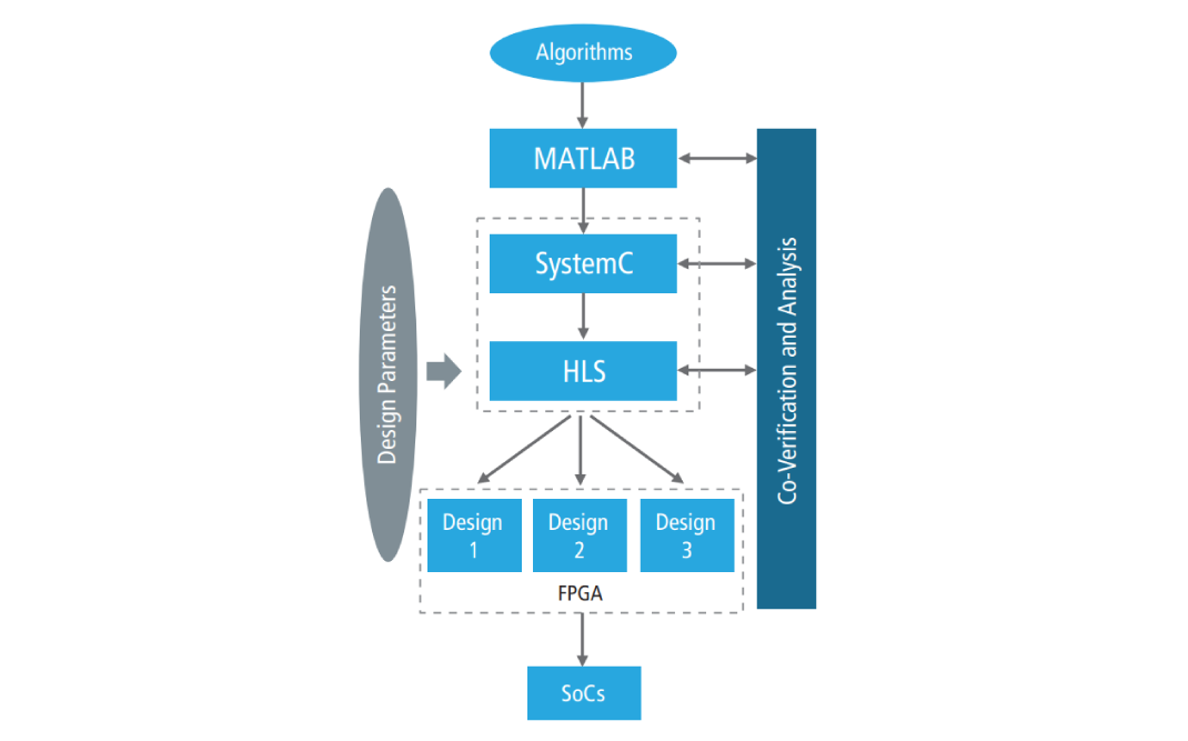
Figure 1: Design flow
A quick note about why we used SystemC: The SystemC class library adds to the C++ language all of the constructs needed to describe the behavior of a hardware design so that they can be simulated and verified, and by using an HLS tool, translated to an RTL format which can be implemented as an IC. The simulation of the SystemC design completes in 1/10th of the time required to run an RTL simulation of the same design, which greatly reduces the turnaround time of trying and testing alternative implementations.
Appling the Design Development Methodology to 802.11ah
Figure 2 shows block diagrams of a typical IEEE 802.11ah client and its baseband sub-block. FFT/IFFT (inverse FFT) and Viterbi decoding are two of the more challenging sub-blocks of the baseband. In the remaining part of this paper, we will elaborate on the design experience of these two sub-blocks.
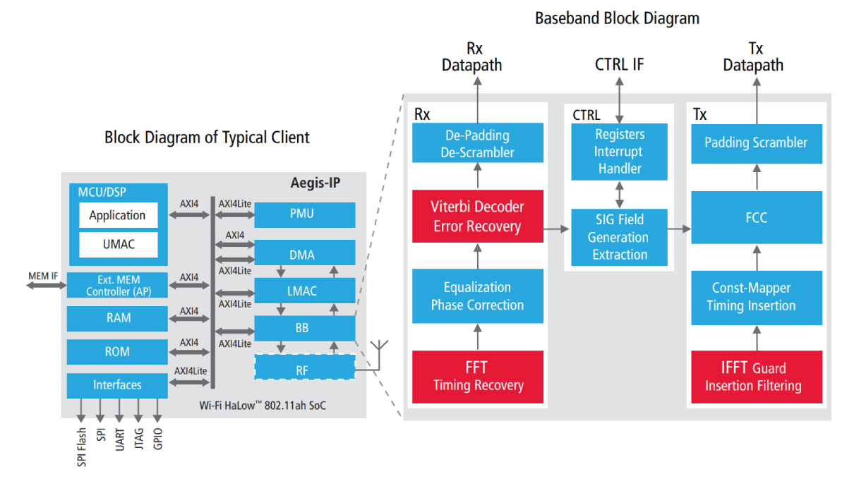
Figure2: 802.11ah Client and Baseband
FFT Baseband Sub-Block
The Fourier transform is used to map digital data onto an analog signal suitable for transmission (the IFFT) and to recover the digital data from the reception of an analog signal (the FFT). The transformation involves a computationally intensive set of vector and array matrix multiplications that can be implemented in a number of mathematically equivalent ways. These methods can have different impacts on the number of gates needed, as well as on the amount of time needed to complete the calculations. In addition, because the 802.11ah protocol optionally supports communication at any of seven signaling speeds, the IP must support multiple sizes of FFT calculation.
To meet this requirement, we coded a flexible FFT routine which:
- Performs any of a chosen subset of 8-, 16-, 32-, 64-, 128-, 256-, and 512-point transforms (the subset chosen by a compile flag, and the particular size chosen by a runtime variable)
- Uses a parameterized fixed-point data type (cynw_fixed type)
- Operates in a “basic” or a “performance” configuration
The “basic” algorithm, when synthesized to RTL, is about 17K gates, and is essentially the textbook implementation computing both FFT and IFFT. The “performance” FFT block employs Winograd factoring, which increases the number of adds/subtracts in exchange for fewer multiplies. We coded both algorithms to support implementation of different-sized FFTs, from 8- and 16-point all the way up to 512-point.
When synthesized to RTL, and after we completed our optimization process, the performance version was significantly faster than the basic version. There was virtually no difference between the performance at a particular FFT point size when we used the compile flag to implement a design that only performs that size FFT, as compared to when we generated an IP that can perform any of the seven sizes of FFT.
We used HLS technology to optimize the combined configuration. In the following paragraphs, we will take you through our journey:
First we created a testing environment for all configurations. Using MATLAB, we randomly generated a large number of test input files and expected result files.
We set up a testbench that would apply each of the test input files and compare the results to the MATLABgenerated result file in a manner that would account for acceptable errors due to the selected fixed-point bit-width.
Second, we implemented the algorithm in C with floating-point computation and the Winograd factoring algorithm. We ran the testbench with this implementation as the device under test, and verified that each input file produced an output file which matched that which was produced by MATLAB.
Third, we implemented the algorithm in SystemC using fixed-point computation. We ran the design with differing fixed-point sizes to find the smallest size which yielded acceptable results, adjusting the testbench error tolerance at this stage.
Having created a design that produces the correct results, and that meets our data processing requirements of error tolerance when run in SystemC, we turned to the RTL part of the project. As a point of reference, the HLS tool we used for this project, when run without any guidance, implements a given design so that it uses the fewest resources possible (area optimized). Since performing the FFT calculation basically entails doing a large number of multiplies and adds, the HLS tool built a circuit with a few multipliers and adders and a set of muxes and registers that cycle data through the arithmetic units many times to perform the calculation.
Next, we began performance tuning of our FFT/IFFT block. The area-optimized implementation performed FFTs in 1,758 cycles for 32-point and 4,022 cycles for 64-point. System requirements mandate that we complete the FFT in less than 1,000 clocks for all point sizes.
We added the synthesis directive HLS_LATENCY (HLS_ACHIEVABLE) to tell the synthesis tool that we wanted the timing-optimized implementation of each of the loops in the FFT. We also added the HLS_FLATTEN_ARRAY directive to tell the synthesis tool that we wanted the various small arrays in the C code to be implemented as individual variables which could be accessed in parallel, rather than as small memories that required serial access to get and put variables. Synthesizing the design with the HLS_ACHIEVABLE directive generated an implementation that performed FFTs in 1,003 cycles for 32-point and 2,464 cycles for 64-point. Adding the FLATTEN_ARRAY directive reduced the cycle times to 876 and 1736, respectively.
Then we took a look at the memory architecture of the design. Initially, the algorithm was written in such a way that real and imaginary parts of the computation were stored in the same memory and multiple pairs of imaginary and real components of data are needed for each multiply and add. To improve performance, we recoded to use two memories – one for the imaginary and one for the real part of each complex data type, indexing both by the same address. This technique doubles the bandwidth of the memory subsystem. Synthesizing the design with the memory changes (and the directives) produced a design that completed in 844 and 1,544 cycles.
We then took a look at the flow of data through the code. Passing data from one routine to another via arguments is a natural C style; however, this requires the data to be copied from place to place, significantly impacting performance (both when run as software and when implemented in hardware). A better coding style passes the data by reference, or holds such data in the class’s data structures, and has the algorithm calling methods to process the data held in the central storage (“object oriented”). Recoding the design to use the objectoriented style and re-running synthesis generated a design that completed in 268 and 519 cycles.
Then we took another look at the memory architecture. As a convenience, the HLS tool converts arrays into memories using naïve assumptions. Explicitly creating properly sized memories at the top of the design (which also serves to identify these for mapping to FPGA memories and ASIC SRAMs) for the real and imaginary arrays and resynthesizing generated a design that completed in 138 and 441 cycles.
Finally, using HLS tool directives to unroll all of the loops (rather than retaining them) and resynthesizing resulted in a design that completed in 96 and 358 cycles. Final results are an 18X improvement in the 32-point FFT and an 11X improvement in the 64-point FFT, as shown in Figure 3.
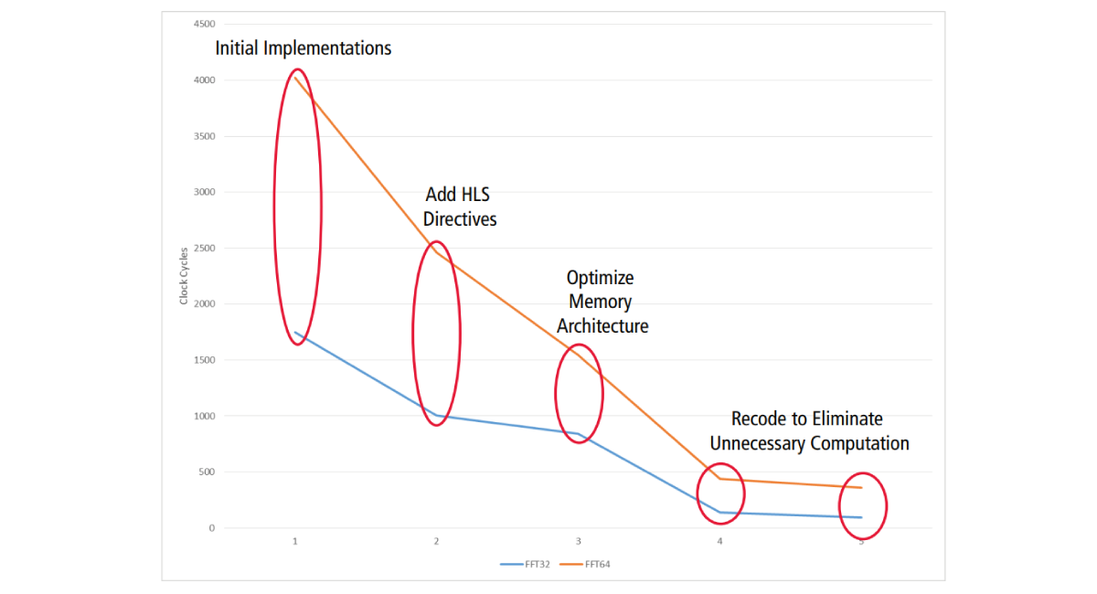
Figure 3: Performance tuning of 32- and 64-point FFTs
Viterbi Decoding
Forward error correction (FEC) represents another major building block in a wireless transceiver. For the transmit side of our FEC sub-block (encoder), we used binary convolutional coding with two polynomials of degree six. The polynomials generate 64 unique combinations with coding rates of ½ and ¾ resulting in 100% or 75% redundancy. On the receive side (decoder), we applied Viterbi decoding to recover the bits and correct any corrupted bits. Decoding follows a three-step process:
- Calculate matrix (cost) units, using hamming distance or Euclidean distance
- Add-compare-select (ACS) and store the accumulated cost in a state table with a depth of 5X-10X the number of possible states (a 64x60 matrix)
- Trace back to extract the decode bits
Figure 4 shows a block diagram of our FEC sub-block.
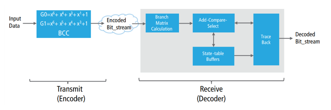
Figure 4: FEC sub-block with Viterbi decoder
The resulting block is computationally intensive, with about 4,000 operations. Since we had a clear idea of three potential architectures which we knew should produce good results, we organized the SystemC code to describe the hardware partitioning we envisioned and applied HLS directives to control the implementation of the various structures. The alternative style (which we employed in the FFT portion described previously) would have been to code an abstract monolithic design and employ HLS directives to partition the RTL and then implement the desired memory architecture. The latter approach would potentially allow us to discover innovative implementations; however, this would likely have required much exploration to get to a basic design that delivers our needed performance.
We experimented with three different implementations:
- Single processing element (PE) and a consolidated 64x64 memory block, which resulted in an unacceptable 550 clock cycles per bit
- 64 PEs and a consolidated 64x64 memory block, which resulted in a still unacceptable 270 clock cycles per bit
- 64 PEs with 64 tightly coupled individual 64-Byte memory blocks, which resulted in a few clock cycles per bit
The initial design took about three weeks to code; and optimizing the design for size and performance took another three weeks. As a result, we saw a 1.5X size reduction and a dramatic improvement in performance, as shown in Figure 5.
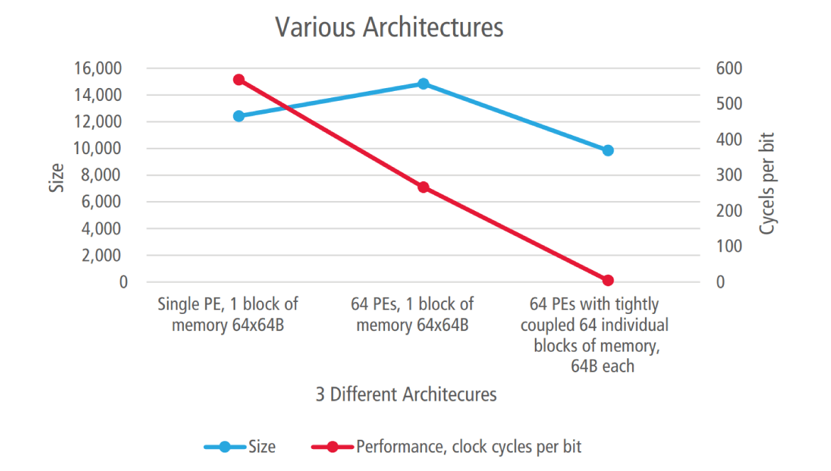
Figure 5: Size and performance tradeoffs
Deriving Designs Optimized for the Access Point and Client Implementations
The 802.11ah standard specifies a central access point interacting with many thousands of clients. Each may be active for only a few minutes a day, sending short status messages. Or, the clients may need to send 300Mbps of video during critical moments. Using the flow described here, we created a single IP that can be used to build the 802.11ah baseband for any application.
The 802.11ah access point is really a communications super computer, exchanging messages at any of seven different bit rates and managing thousands of clients. It also provides backhaul communication from its clients to the Internet. An 802.11ah access point SoC would typically be implemented at 28nm or smaller, and a few of these would be deployed across the enterprise.
The simplest 802.11ah sensor node is almost a “deploy once and forget node” (akin to an RFID chip) that may be integrated into an appliance or shipping container. These simple sensor nodes need to communicate only at the slowest bit rates, and once such sensor nodes reach the end of their battery life, the host appliance is expected to have completed its service life. Such 802.11ah sensor node SoCs will be implemented in very low-cost, low-leakage technologies such as 90nm or 180nm.
The HLS tool accepts the technology library as one of its inputs, enabling us to generate a design optimized for the 28nm or the 180nm node. We coded the baseband so the supported bit rates and communication protocols can be selected via a compiler variable, enabling us to generate a feature targeted design for the chosen application. Given this, we can, from the same source, generate a performance-optimized baseband for use in mission-critical access points, as well as baseband for low-cost, throwaway sensor nodes, by using different script files to control the selection of technology library and compiler configuration options.
Lessons Learned from FFT and Viterbi Optimization
As we developed our behavioral IP, we generated the performance we wanted and also decreased block size by approaching the effort as a design refinement. We also learned a few tips and tricks along the way:
- Do not code as if instancing a specific number of resources, unless the algorithm cannot be expressed in any other way. Otherwise, there’s a risk of reducing the HLS tool’s ability to optimize your design.
- Do not inline or unroll because you think the tool can’t do this for you. There are directives for this, if needed. Code naturally, and let the tool do the bookkeeping.
- Do not add synthesis directives in advance of the need to force a change in HLS tool behavior, as you risk slowing down synthesis.
Summary
As part of our HLS flow, we used Cadence Stratus High-Level Synthesis (HLS). Stratus HLS features an integrated design environment for creating abstract SystemC, C, or C++ models and synthesizing optimized hardware from these models. These models can then be reused more easily and broadly than can traditional hand-coded RTL.
Had we used an alternate method to create our IP, such as SystemC to Verilog, we would have had to maintain multiple databases and the process would have taken longer to converge. Our work on the FFT block was completed in just two man-months, and about one-third of this time was spent on design refinement.
Using HLS to create reusable IP does require discipline with the experimentation used to optimize the design. In our case, as we refined our design, we carefully tracked the resulting effects and also compared results, moving ahead so long as we continued to see forward progress. Based on our experience, the HLS design flow delivered a dramatic design cycle reduction, flexibility to easily change our design, the scalability to support multiple designs from the same database, and a final product with the optimal power, performance, and price.
For Further Information
Learn more about Stratus HLS.
Learn more about Adapt IP.
Learn more about the 802.11ah IP discussed in this paper. The Adapt-IP 802.11ah baseband, together with the Methods2Business 802.11ah MAC, are available as an integrated IP.