White Paper
How High-Level Synthesis Was Used to Develop an Image-Processing IP Design from C++ Source Code
Methodology helped accommodate late spec changes on aggressive delivery schedule
Imagine working long and hard on a design, only to learn that you need to add new (and more complex) functionality a few months before your targeted tapeout. How can you deliver the performance and capabilities expected in the same timeframe? For Bosch, high-level synthesis (HLS) provided the solution. In this paper, we will discuss how HLS technology enabled the team to meet an aggressive schedule on its image-processing IP without any changes to its existing floorplan.
Overview
Introduction
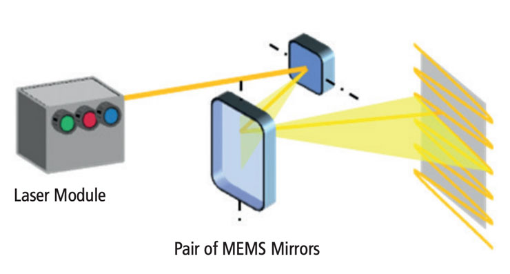
Bosch has developed a technology base for laser scanning projectors (Figure 1) for multiple use cases in automotive, consumer, and industrial applications such as head-up displays and collaborative robots, as well as for embedding into mobile devices. Designed with a pair of MEMS mirrors, the laser scanning projection system provides focus-free projection with high image quality and reliability in a small form factor. It requires no optical elements.
When the ASIC engineering team received the request to add complex new functionality to the pico projector, the engineers quickly recognized that handcoding the new design elements and verifying them using a traditional flow would mean missing their delivery schedule.
Collaborating with Cadence, the Bosch engineers took their existing SystemC model through an HLS flow and got verified RTL code in return, right on schedule.
Re-Implementing Blocks in the Image Pipeline
Bosch’s pico projector design consists of four key modules:
-
 MEMS module with a horizontal mirror and a vertical mirror
 - Laser module with photodiodes and RGB laser diodes
- Power management module with supply regulators and laser diode driver
- ASIC running MEMS control and image-processing algorithms
The image-processing algorithm was developed in behavioral SystemC code, with the initial RTL written by hand. Roughly 12 weeks before scheduled tapeout, the ASIC engineering team received a change request to the algorithm. This change required the engineers to re-implement some blocks of their image pipeline, with these constraints:
- The area could not exceed what was originally established, so the floorplan would not have to change
- Clock gating should be nearly 100%
- The ability to easily change the SystemC code was important
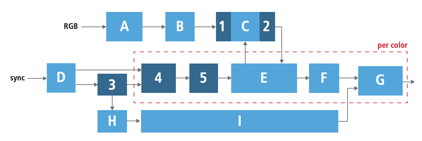
Figure 2 shows, in dark blue, the blocks that needed to be changed in this design. Given the schedule and available resources, the team did not have time to re-implement their RTL manually for these blocks. Adding to the challenge, the engineers who originally designed the blocks in question had been assigned to other projects by this time and were, thus, unavailable. Familiarizing other designers with the blocks and code would have taken too long.
The ASIC engineers had a service agreement in place with Cadence and presented their challenge to their Cadence applications engineer, who was already working with the team on tasks including back-end place and route on the digital blocks of their design. The applications engineer introduced HLS to Bosch as a pilot project.
The Bosch team already had a SystemC model in place for virtual prototyping and recognized that they could use this model to generate some fast results. So, using HLS made a lot of sense. Together, the Bosch and Cadence engineers implemented an HLS flow.
HLS Flow
After demonstrating the effectiveness of HLS using the Cadence Stratus High-Level Synthesis (HLS) tool on one module in Bosch’s design, the engineers implemented the changes needed on the remaining pipeline blocks.
Bosch provided interface specifications and bit-accurate behavioral SystemC code, as well as a reference model for functional validation of the RTL. Verification was based on SystemC-RTL co-simulation and bit-level I/O comparison, providing a short path from reference simulator to verified RTL.
One early issue encountered was that the SystemC code consisted of fixed-point arithmetic implemented with the Accellera fixed-point types, which cannot be synthesized. But the team created a compatible, synthesizable version by spending a couple of minutes changing a header file (no code changes were needed).
The resulting code could then work with a synthesizable version of the fixed-point library included in Stratus HLS that is compatible with the Accellera fixed-point types. The engineers could retain the OSCI fixed-point library in the testbench, which provides richer semantics for simulation-only constructs. And they could use cynw_fixed in the designs under test (DUTs) to be synthesized.
The effort called for two deliverables:
- Working RTL for all blocks
- Quality of results (QoR) compliance for all of the blocks
With bit-accurate data types, the Stratus tool was able to utilize the minimum required amount of bits for the best QoR. Because there was a one-to-one correspondence between the hardware blocks and functions in the simulator, the team was able to easily encapsulate a function in an SC_MODULE and feed it into Stratus HLS. It was also straightforward to map function arguments and return values to hardware I/Os, so the team could easily encapsulate function call arguments in signal-level hardware protocols.
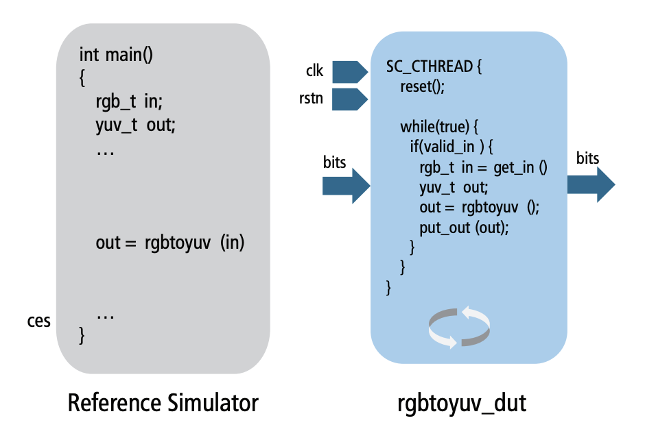
Creating the DUT
Bosch and Cadence created the DUT using these steps (Figure 3):
- Create SystemC module structure
- Add I/Os
- Create a SystemC thread
- Add a reset
- Wrap the behavior in an infinite loop
-
- Add I/O protocols for the operands via IP provided with Stratus HLS
- Convert sc_(u)int data types at the interfaces into application-specific data types and vice versa
-
- Copy the relevant functions from the simulator as the module’s main behavior
-
- Repeat for each block
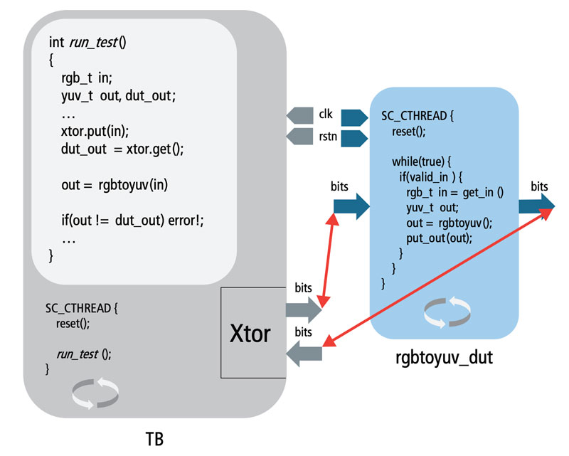
Building the verification environment involved these steps (Figure 4):
- Create testbench from the simulator
- Execute the test as a SystemC thread
- Drive clock and reset
-
- Interface the testbench with the DUT
- Create transactor with the DUT-specific I/O protocol
- Feed the same data to the DUT
- Retrieve the result and verify locally
-
- Interface the testbench with the DUT for each block
Results
For the Bosch team, the key advantages of using HLS was being able to stay on their aggressive schedule despite the late specification changes to their image-processing IP design. Beyond the quick turnaround time from the specification change to new RTL, keeping the area below the original design allowed the existing floorplan to remain in place, minimizing impact on the back-end implementation flow.
Had they designed to the new specs manually, they likely would have needed more architectural exploration—and, thus, more time—to fine-tune the design to fit the smallest area. Stratus HLS offers many “knobs” to explore a variety of micro-architectural implementations for the same functional specification. As a result, the team was able to configure parameters such as pipeline depth and throughput, and determine the implementation that minimizes area and/or power to achieve comparable or even better QoR versus handwritten RTL.
Compared to handwritten RTL code with the original functionality, the resulting HLS code was about 5% smaller and, compared to the target, required about 9% less cell area. Clock gating was 98% overall, close to the overall target of 100% that was initially desired. See Figure 5 for a table showing results for the final deliverable.
| Module | 1 | 2 | 3 | 4 | 5 |
|---|---|---|---|---|---|
| #instances | 1 | 1 | 2 | 8 | 4 |
| Target area [NAND2] | 1800 | 1200 | 57100 | 8300 | 3200 |
| #FFs | 27 | 54 | 733 | 85 | 19 |
| #CGC | 1 | 2 | n/a | 3 | 1 |
| Clock gating | 96% | 93% | 99% | 93% | 95% |
Summary
With an aggressive delivery schedule and complex new functionality to integrate into its image-processing IP design, Bosch couldn’t afford the time commitment that using handwritten RTL would have required. Working with Cadence on an HLS flow enabled the engineers to stay on schedule and meet performance/power targets for their design. The team delivered SystemC code and received verified RTL code in return. What’s more, no changes to their existing floorplan were necessary. HLS proved to be an efficient means for Bosch to accommodate a change request that came just 12 weeks before scheduled tapeout.