Content Type
AWR Visual System Simulator
Communications and radar systems design software
Cadence AWR Visual System Simulator (VSS) communications and radar systems design software within the Cadence AWR Design Environment platform supports realistic measurements of mixed-signal (RF/digital) networks and cascaded RF blocks. It helps identify the source of spurious products and system metrics such as bit error rate (BER), all from a single system diagram. Designers of commercial and military transmitters and receivers can then create subsystem architectures, specify component requirements, and optimize for best overall performance.
Overview
AWR Software Platform
Conceptualize and rapidly implement virtual 5G New Radio (NR) and internet of things (IoT) communication and radar/ electronic warfare (EW) systems using RF/microwave and signal processing blocks based on measured, simulated, or projected behavior to investigate new architectures and study overall system performance.
Design RF-aware systems and perform rigorous link budget design with RF/microwave behavioral models that incorporate linear and nonlinear performance metrics as well as terminal impedances that lead to power loss due to component-to-component impedance mismatch.
Validate RF circuit specifications by co-simulating with Cadence AWR Microwave Office circuit design software for RF/microwave design, as well as the AWR Design Environment platform’s Cadence AWR AXIEM planar and Cadence AWR Analyst arbitrary 3DEM solvers, to support communication measurements for individual components and validate component specifications to meet system requirements.
Product Strengths
Digitally Modulated Systems
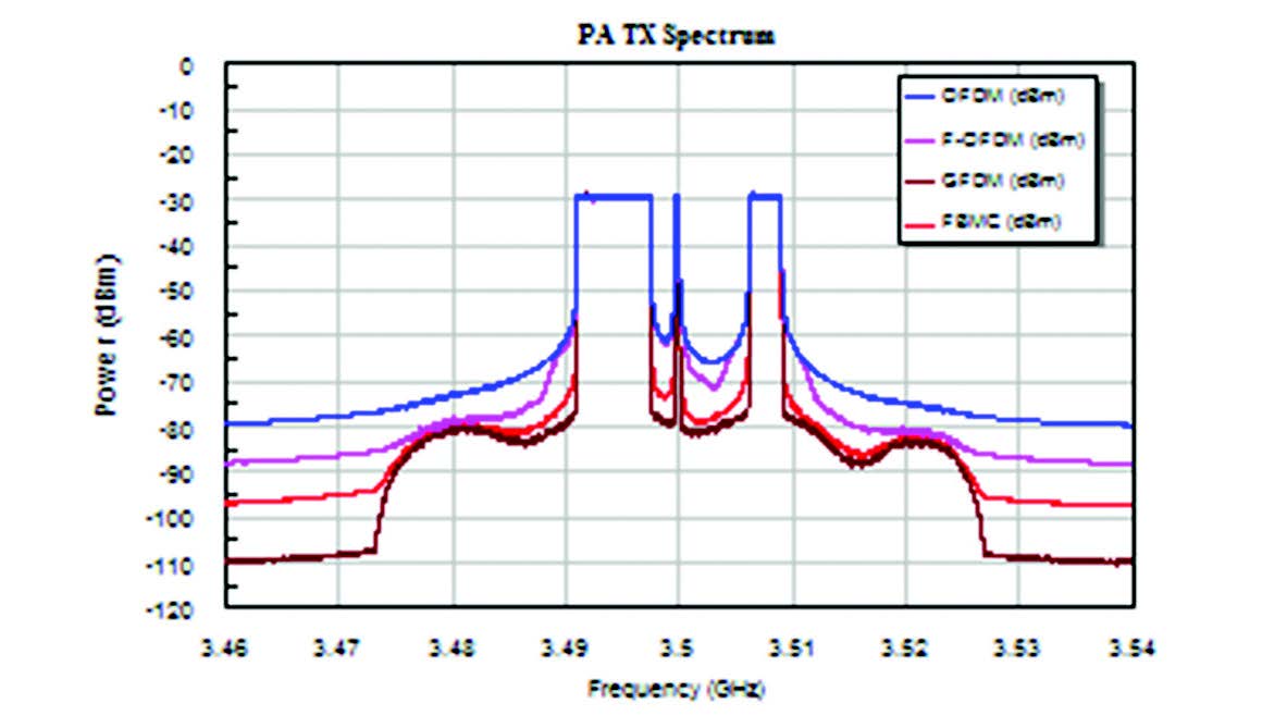
Design and simulate system architectures and components with IP libraries for wireless communication standards, including LTE-A, 5G, narrowband IoT, and more. Preconfigured testbenches support transmitter conformance testing and receiver sensitivity analysis, as well as circuit co-simulation, for linearity measurements such as adjacent channel power ratio (ACPR) and BER of power amplifiers (PAs) operating under high peak-to-average power ratio (PAPR).
Link Budgets and Spur Analysis
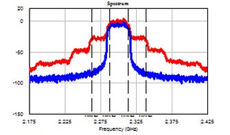
Perform RF-cascaded measurements such as gain, noise figure (NF), and third-order intercept (IP3) while accounting for impedance mismatch throughout the signal path. The AWR VSS RF Inspector (RFI) frequency-domain simulation tool that helps designers identify frequency content (harmonic and intermodulation tones arising from device nonlinearity) anywhere along an RF link.
Phased Array Systems
Simulate critical antenna performance in phased arrays with a reconfigurable model supporting thousands of radiating elements based on measured or simulated antenna data for the development of beamforming algorithms, evaluation of hardware impairments, and RF link analysis.
The unique, open, and integrated environment of VSS enabled us to study the effects of the nonlinear distortion on our communications link margin using real digital modulated analog waveforms.
Stephan VanFleteren, General Dynamics
Hardware in the Loop
Plug-and-play support for co-simulation with LabVIEW, MATLAB, and C++ expands modeling capabilities with custom models, automation scripts, and user-defined signal processing algorithms.
Testbenches
Testbenches are pre-configured for common measurements such as ACPR, error vector magnitude (EVM), spectral, and many other types of measurements. For instance, preconfigured testbenches with 5G NR signals and measurements support performance verification of components or subsystems with 5G NR standard test model signals.
5G/Radar Library (Option)
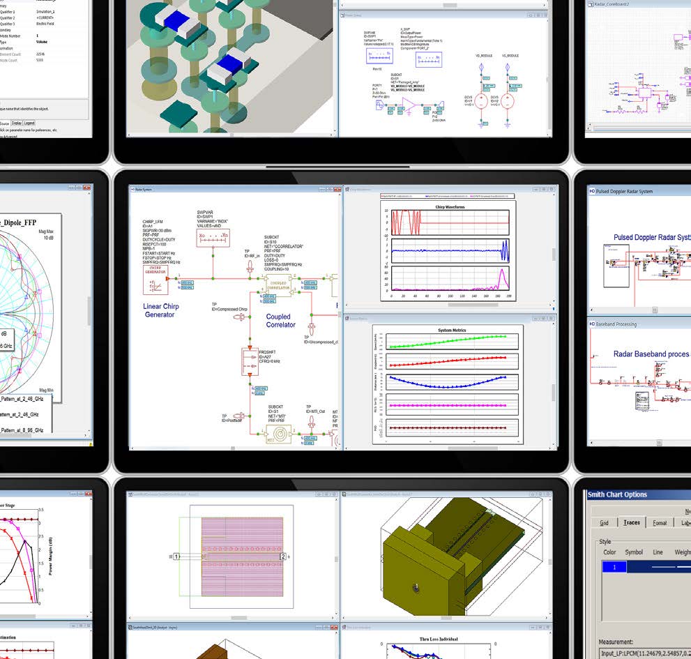
The 5G/Radar library offers easy-to-configure signal sources and receivers that can be used for evaluation of RF components and/or RF links used in radar and 5G systemlevel measurements.
Preconfigured measurements for 5G NR transmitter components include complementary cumulative distribution function (CCDF), AM to AM/PM, spectrum, EVM, ACPR, IQ constellation, and more. 5G NR receiver simulation sensitivity measurements include BER, block error rate (BLER), and throughput.
For radar applications, the library offers radar signal generation, radar-specific target and propagation modeling, and radar signal processing capabilities, including moving target indicator (MTI), moving target detector (MTD), and constant false-alarm rate calculator (CFAR).
Features
Applications and Technologies
RF System Models
RF system models include RF behavioral, file, and circuitbased models that quickly perform frequency-based cascaded measurements such as cascaded NF or operating gain or identify the makeup of frequency content at any point in an RF link using the RFI tool. RF modeling applies to the portions of a system design that represent analog voltage signals, usually at RF frequencies but not always. These are the portions of the design that include behavioral amplifiers, mixers, and circuit-based filters, as well as blocks for incorporating AWR Microwave Office circuit designs within a system simulation.
Communication PAs
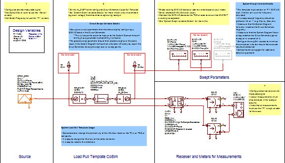
Preconfigured testbenches supporting the latest 5G signals and frameworks proposed by various industry groups allow designers to simulate and optimize the performance of RF front-end components such as PAs based on PAPR, adjacent channel leakage ratio (ACLR), EVM, or any number of critical amplifier performance metrics, as well as identify the source of spurious products and other system impairments. System-level load-pull analysis generates contours for communication performance metrics such as ACPR and EVM, allowing designers to optimize impedance-matching networks for linear PAs used in wireless communication systems.
Phased Array Generator
The phased array generator wizard within AWR VSS software enables designers to interactively design a phased array antenna and then generate schematics or system diagrams that represent the design. Quickly configure planar phased array or multiple-in-multiple-out (MIMO) array systems, interactively modify designs to achieve the desired behavior, and generate system diagrams and/or circuit schematics and electromagnetic (EM) structures for further, more rigorous analysis. The wizard supports interactive specification of the layout, feed network settings, element antenna and RF link settings, gain tapers, and element failures.


